Nelson Pass said:There are three typical causes for intermittent mechanical hum
from the transformer.
1) Your circuit might intermittently draw very large amounts of
current. This is not very likely.
2) Your AC line might have some DC type noise on it, which
saturates the transformer. Lamp dimmers and other Variac
type controlled equipment are the usual culprit, and a filter
network is the usual answer.
3) Your secondary system might be drawing, on average, more
current from one rail than the other, in other words, different
+ to ground than - to ground. If the secondary windings are
mismatched and you are using only 1 rectifier bridge for the
two polarities, this can cause the same kind of saturation as
in (2). This is common when there is high DC offset at the
output through the speaker. Besides balancing out the draw,
you can also cure it by providing one rectifier bridge for each
rail polarity, assuming that you have dual secondaries and
not just a center-tapped secondary.

Is (3) more likely when two transformers ares used? (one for each rail)
1) Is not the case.
2) Is not the case unless 1mV DC average is too much. When the hum occurs the DC doesn’t rise. Max DC is 2.235mV measured over a period of 30’.
3) I can’t imagine both amps draw unequal currents exactly at the same time when not playing any music. Dc at the output is quite stable and within specs range.
The hum occurs definitely when my neighbour is welding.
I am however not able to measure big differences in the AC power condition then.
So how would a filter network look like?
I found an example in Elektuur, showing 2 100nF capacitors and a 30µH choke in between. I made it a time ago but never used it.
/Hugo
Attachments
I'm curious about the influence of an AC filter in a power amp.
Mr Pass, do you use them in your products? (power amps and other)
Mr Pass, do you use them in your products? (power amps and other)
is there a possibility you have a common earth link with your neighbour?
If so, make your own...
If so, make your own...

A filter like this one will block mains DC (C1/4 and D1/2/3/4, the rest is EMI filter).
Another thing you could try is using a Zobel snubber on the secondaries, as described here (while I've used this to get cleaner power, in one case is shut up a singing transformer; but good luck calculating the correct values if you don't know the parasitic capacitance and inductance of the transformer, maybe trial and error...)
Another thing you could try is using a Zobel snubber on the secondaries, as described here (while I've used this to get cleaner power, in one case is shut up a singing transformer; but good luck calculating the correct values if you don't know the parasitic capacitance and inductance of the transformer, maybe trial and error...)
Thanks Prune, I missed that thread.
I could eventually try such a filter but as I stated above, there's no real measurable DC in the AC-line. Or would 2.2mV already cause problems?
/Hugo
I could eventually try such a filter but as I stated above, there's no real measurable DC in the AC-line. Or would 2.2mV already cause problems?
/Hugo
2.2mV DC probably is too low to be a problem. Try my second suggestion then, hopefully that may help, (and if not, at least you get quieter power).
Circuit Board
Hello,
I see in post 5 that you just used a circuit board (with point to point soldering?). Would this be difficult? I would like to try this out for the high powered version of the Aleph-X.
Hello,
I see in post 5 that you just used a circuit board (with point to point soldering?). Would this be difficult? I would like to try this out for the high powered version of the Aleph-X.
It needs a bit more attention than plugging parts into a pre fabricated board but difficult? No. Try it, it's real fun and a good challenge when you like puzzles. 🙂 I would make a paper drawing with part numbers for ease of troubleshooting and tweaking later on.
Netlist,
Thank you for the advice. Would have a prefrence on Circuit boards that would work well for this application?
Thank you for the advice. Would have a prefrence on Circuit boards that would work well for this application?
I tried - later on - with the famous BrianGt or Peter Daniel boards (don't recall) but in my case they needed some compensation caps to prevent oscillation. Apart from that they were very nicely made and I would think hard to find.
/Hugo
/Hugo
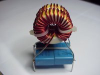
Maybe you could "unwind" the transformer ?
Take a few secondaire windings of, i did it to, to go from 30 to 28 volts.
Regards,
Nick
Take a few secondaire windings of, i did it to, to go from 30 to 28 volts.
Regards,
Nick
so unwinding secondaries does lower the voltage of the secondary? If i buy a 65 volt transformer, will I be able to unwind secondary coil until it reaches an output of 40- 20 volts?
yup
but , that will leave you with undersized thickness of secondary wire
it is calculated for original VA of xformer , and when you unwind more than 10% , wire is too thin to cover full VA capacity of core/initial xformer configuration
but , that will leave you with undersized thickness of secondary wire
it is calculated for original VA of xformer , and when you unwind more than 10% , wire is too thin to cover full VA capacity of core/initial xformer configuration
- Status
- Not open for further replies.
- Home
- Amplifiers
- Pass Labs
- Industrial AlephX High Power version