I finished assemble and testing, and hearing for 3 hours the last Graham Maynard design...he sent me july, 8.
A 100 watts over 4 ohms amplifier, class A to AB, having enormous identities with circuits of our days, and some differences that produce, all together, a very incredible amplifier.
I think he will publish very soon..... do not let to assemble this one, and tell me if i am wrong.
ahahahaha!...can call me Charlotte if less than 99 percent of guys completely astonished and satisfied, the ones that decide to produce this unit will have enormous satisfaction.
Prepare your boots to kick a lot of amplifier.... a genuine S kicker is arriving soon.
Yeah!...i already love AKSA 55, but this one have complementary qualities...better to have both.
regards,
Carlos
Hi Carlos,
I know you've had troubles recently, but you are happy smiling there !
I had already posted the circuit in Lumanauw's thread entitled the many faces of distortion, but here it is again.
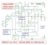
Carlos tells me he is using a single class-AB 2SA1216/2SC2922 output pair with 2SA1837/2SC4793 drivers. With a 2SC1819 video transistor for the voltage amplifier he had to fit 50pF across its base-collector legs to prevent oscillation. At least the circuit works with transistors other than those shown, though I can touch anywhere in my amplifier with a wetted finger against a screwdriver blade and there is still no oscillation.
My main aim with this circuit was to make it have low first cycle distortion/ good transient capabilities by making it have a very low internal inductance. Thus dynamic loudspeaker system generated back-EMF should cause minimum amplifier-loudspeaker interface reaction, with the sound remaining neutral.
Imagine the JLH four transistor class-A.
Add 'helper' class-AB push-pull drive to incresase power and efficiency.
Add a differential input pair for output voltage zero control, but note the 10nF capacitor that retains two stage hf stability.
Add a mirror to prevent power-up thump, but note its 220nF capacitor again for two stage hf stability; ie. mirror at audio frequencies, CCS at hf.
It runs with constant class-A control, and yet has decent class-AB output powering capabilities.
Cheers ........... Graham.
I know you've had troubles recently, but you are happy smiling there !
I had already posted the circuit in Lumanauw's thread entitled the many faces of distortion, but here it is again.
Carlos tells me he is using a single class-AB 2SA1216/2SC2922 output pair with 2SA1837/2SC4793 drivers. With a 2SC1819 video transistor for the voltage amplifier he had to fit 50pF across its base-collector legs to prevent oscillation. At least the circuit works with transistors other than those shown, though I can touch anywhere in my amplifier with a wetted finger against a screwdriver blade and there is still no oscillation.
My main aim with this circuit was to make it have low first cycle distortion/ good transient capabilities by making it have a very low internal inductance. Thus dynamic loudspeaker system generated back-EMF should cause minimum amplifier-loudspeaker interface reaction, with the sound remaining neutral.
Imagine the JLH four transistor class-A.
Add 'helper' class-AB push-pull drive to incresase power and efficiency.
Add a differential input pair for output voltage zero control, but note the 10nF capacitor that retains two stage hf stability.
Add a mirror to prevent power-up thump, but note its 220nF capacitor again for two stage hf stability; ie. mirror at audio frequencies, CCS at hf.
It runs with constant class-A control, and yet has decent class-AB output powering capabilities.
Cheers ........... Graham.
Attachments
As you told me, my needed modifications made will be shown here.
Sounding great Graham.
Thank you very much, i am very happy with this amplifier.
Here is the schematic, with the option to change the 2SC1819 by a 2SC4793 or other that belongs to your own preference.
Those transistors are very good, and they are used in wonderfull amplifiers.
But you can change a lot of things, including the input transistors....yes, i changed for a 300 Mhz unit...but could not feel diferences.
My circuit can have defects, or errors...but i guarantee that is sounding very good and working for 5 hours without any problem.
regards,
Carlos
Attachments
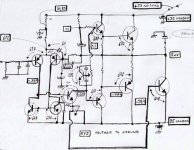
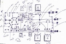
Here is some information related voltages.
The voltages measured referenced with ground are inside square lines.
The voltages with arrows are VBEs
The supply is simple with 15000 plus 15000uF
The supply voltage without load is 37 volts plus and minus, when amplifier adjusted, my supply measured exactly 35 volts plus and minus.
I am using 8 ohms speaker....also hearing with Phillips good headphones with 220 ohms in series...wonderfull sound!
Power consumption is 550 miliamps in stand by mode.
heatsink total of 1600 squared centimeters of air exposed area.
Inside my supply there are two transformers, each one of them around 250 to 300 watts.... separated filters and rectifiers, the output is joined together...two supplies in parallell, as voltage is almost identical...have 100N bypass capacitors inside, connected from plus to ground, negative to ground and positive to negative also..... 500 volts poliester units.
Sorry, the image is not so good, needed some effort to read voltages there.
regards,
Carlos
Attachments
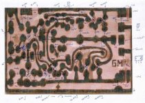
One sketch, an idea to produce your board
If you like to make your own boards, a hand work, here is some idea.
You can sketch with parts drawn.....At same time you can see the other side copper lines.
Imagine this board as something made with glass, completely transparent...so, you can see the other side lines, and the parts that will soldered over.
I use to solder over the copper, this way i have not to make holes and have not to invert nothing.
And sound without holes is good, also sound of parts soldered over copper are good too...no difference.
As board will be inside enclosure, and i will not watch it many times, it can be ugly...no problem....but have to sound good.
Because pretty board and sound bad...trash box is the place.
regards,
Carlos
Attachments
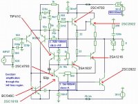
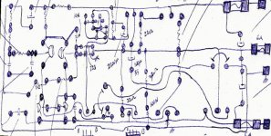
Check it all, as i use to produce some errors.
Just some idea to you.
This amplifier is easy to construct, seems confused because the way was drawn to fill one Tina small screen.
But in reality it is simple and very standard in the main thopologie, some details are different only.
here some vision more close.
regards,
Carlos
Just some idea to you.
This amplifier is easy to construct, seems confused because the way was drawn to fill one Tina small screen.
But in reality it is simple and very standard in the main thopologie, some details are different only.
here some vision more close.
regards,
Carlos
Attachments
It can work fine with 30 milivolts over emitter resistors, working class AB
I adjust it to class AB and the unit works fine....not so good as class A.
To adjust to class A have to advance bias trimpot and read more than 110 milivolts over 0.22 ohms resistors.
Well, Graham informed that have to adjust 400 miliamps for the standard output, and then increase more 100 miliamps adjusting the extra NPN transistor bias.
I could hear....yes HEAR, around 10 Hertz, and full output was obtained at 16 Hertz, related the superior limit, i could not test, as my computer do not produce tones with frequencies higher than 15 kilohertz.
But hearing White noise and Pink noise, i could perceive it goes very high...including the harmonics to reproduce bells and wistles.
This is the first time i perceive deep bass here in my small burn transistor place.
regards,
Carlos
Graham, Carlos,
I think this amplifier design is extremely clever; it uses a very innovative, hybrid approach.
Congratulations! You have richened the art........
Cheers,
Hugh
I think this amplifier design is extremely clever; it uses a very innovative, hybrid approach.
Congratulations! You have richened the art........
Cheers,
Hugh
Very nice your words Hugh, but you can see, there's the good bootstrap
And if you observe, there's a Miller capacitor, despite Graham dislike it, my unit oscilated because of transistor made.
I will fix, following Graham instructions....who am i to discuss with Graham?
The Same output topologie you have in Aksa 55 and some clever ideas from Graham....this is all Graham design, i am just following his progresses and constructing some amplifiers.
Another interesting is Symassym version 4, but MikeB disappeared when i told him that step by step he was changing his amplifier to be an AKSA....ahahahaha....i think he did not like the comment...... a long research, and changing here and there....a hard work....when i saw the output...there's the Aksa.
He disappeared...may be with redish face near Andromeda Constellation.
Live is beautifull, and our friends are wonderfull.
Hey Hugh!...do not tell the guys!...between you and me... some secret, ....he was near to produce one Aksa...ahahahahaha!
regards,
Carlos
My next amp of comparison( technical and acoustic ).
I am a little worried by the Carlos enthusiasm. We hope that Graham leave still some chance of amelioration! 😀
Joking aparts, is a lot of interesting to build a amp so "simulated" and studied by Graham, because allows to all we of make a will in the reality his convictions. his availability to furnish her backgound ( and the schemes ) shows ( if there from it were be necessary ) her "genuine" passion for this subject.
Am not much the planners prepared for himself put " in play ", but surely is the better thing...
Ciao
Mauro
Out of Topic
Mauro,
No offence to you Mauro but could be offensive to others. Even if we know that this was not your intention.
We all are, to some degree, limited with languish but reading your last post called my attention the way you refer to Graham.
He, his, > refer to a male person.
She, her > refers to a female person
Someone had to tell you
🙂
Va molto benne fratelo Mauro, It's all rigth brother Mauro
I feel good when i found a good amplifier, already assembled more than 2.5K units...maybe 2.7K....and i am very tired of assemblage.
This amplifier, as many Graham designs sound great, also Aksa 55 is a wonderfull amplifier and also the Symassym4 is very good.
I can find more 5 or 6 good units...the rest....hummm...capiche?
Your flag, seem Italy..but i am not sure uomo... va molto benne.
regards,
Carlos
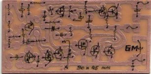
Here is the board i prepared this morning.
It is self instructive.
I use to solder direct over copper, but you can transfer to the other side without too much work.
The board size is 90 X 45 milimeters.
A little more than 3 inches and a litle less than 2 inches...ahahaha!
The TO-220 transistors and the output are connected to the board using thin twisted wires...not too long, as you may have 1 picofarad of capacitance each inche...so...keep them short.
Over the board only the small transistors of the differential amplifier and CCS
regards,
Life is wonderfull, having amplifiers to assemble.
Carlos
Attachments
Alô Hermano del Sombrero, Hello my friend of the Mexican Hat.
Graham is a wonderfull person, he will not bother related that small mistake made by Mauro....hehe, try to follow the awfull things i wrote here.... confusion of whole with hole....beach with.... my God!... forum friends need to have patience.
Olá hermano, es un placer mui grande recibir el hermano que arriba sin embargo.... yo no hablo espanhol...solamente Portunhol.
Hello brother, is a big pleasure the brother land here is this forum, without doubts i do not speak Spanish, only some strange language that is something between Portuguese and Spanish.
Bienvenido nesta thread...welcome this thread!
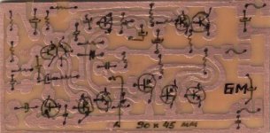
One transistor was missed.... a new image.
Do not construct without check my board...i guarantee that will explode, as normally happens here..... understood....Destroyer Extra?
Saludos
Carlos
Graham is a wonderfull person, he will not bother related that small mistake made by Mauro....hehe, try to follow the awfull things i wrote here.... confusion of whole with hole....beach with.... my God!... forum friends need to have patience.
Olá hermano, es un placer mui grande recibir el hermano que arriba sin embargo.... yo no hablo espanhol...solamente Portunhol.
Hello brother, is a big pleasure the brother land here is this forum, without doubts i do not speak Spanish, only some strange language that is something between Portuguese and Spanish.
Bienvenido nesta thread...welcome this thread!
One transistor was missed.... a new image.
Do not construct without check my board...i guarantee that will explode, as normally happens here..... understood....Destroyer Extra?
Saludos
Carlos
Attachments


Re: Tony del torreón...languish was wonderfull
jejjeje, you are right Carlos 🙄

destroyer X said:Lânquido es mucho sexy!...ahahaha!
I do not now the English translation...let's see...language!...yessss!...my God!
Carlos
jejjeje, you are right Carlos 🙄
- Status
- Not open for further replies.
- Home
- Amplifiers
- Solid State
- Incredible quality amplifier by Graham, prepare your ears for it