As JMFahey said, 100 v units are too close to the limits
Use higher voltage ones for safety.
Can't be too expensive, and you can use single 15000 uF/120V in place of 2 units 8200 uF.
Use higher voltage ones for safety.
Can't be too expensive, and you can use single 15000 uF/120V in place of 2 units 8200 uF.
I would rewire the capacitors to separate lines instead of the series arrangement, use 160v rated on the higher voltage rail, direct to ground. Or even higher rated, if they are available and cheaper as 200V and 250V are typical SMPS voltage ratings.
Typical sloppy design from small time makers.
If there is a surge in supply, your expensive caps will blow up.
Or see if you can find another, better one within your budget.
Typical sloppy design from small time makers.
If there is a surge in supply, your expensive caps will blow up.
Or see if you can find another, better one within your budget.
Last edited:
Deton is made in China, and in sufficient quantities they will put your name on it as well.
I wonder how it sounds in comparison to Japanese and European amplifiers.
And those capacitors were dry...
Do not expect the amp to run at its claimed rating for a long
time.
Taicon is a brand which is made in Taiwan, the company is a licensee of the Japanese manufacturer Nichicon. It is reputable for capacitors.
Thicon is a deceptively similar name.
The whole unit is a badly made cheap knock-off.
Last edited:
Aw man, that’s harsh…. I get your point around the caps being too close to the limit. In hindsight I should have tried finding higher rated ones. To be fair I’m not intending b to run this amp at its load limit. I just picked it up to tinker with it. Some romantic notion of massive power reserves. Next time I’ll do more research before picking up a project.
When the electrolyte has dried up and pins are missing its not surprising to rattle when the innards shrunk and lost support.The caps also rattle when shaken. Is that normal?
The quick and dirty solution is to have a step down transformer.
I had this problem with LED lamps blowing up, and the solution suggested was to use a 350 v primary / 240 v secondary, that would reduce the supply to within the driver rating of 85 - 277 volts...
The drivers would fail at late night, when the whole grid was lightly loaded, the primary side would go high, we would see more than 300 volts on the secondary side.
Ultimately the problem was solved by adjusting the transformer output using the tap changer on the primary side.
It is a 11 floor building in Kampala, I am in India, so it was a little awkward to send new ones. You don't get such quality stuff in Uganda.
So please bear in mind what you want to do, this unit is not going to be reliable given its design and parts quality.
Deton is deceptively similar to Denon, and back in the days we used to get Tony audio cassettes, similar to Sony! There were even Coney branded cassettes...
Thing is, it is made to a price, and sometimes compromises are made.
Rattling caps also happen when a small capacitor is put inside a big housing.
It is done by radio restorers to preserve the looks, and by fakers, who are rather more numerous these days...
Last edited:
I got 100v ones as anything else is prohibitively expensive. I understand that they will likely only last 10 or so years.
They better be 105C temperature rated. The original ones were 85C and close together. If they were working inside or near a hot air ventilation stream, that might be the main reason of the sorry state they ended up in.
I don't think temperature was the killer, as the dry ones were on the outside of the cap cluster, the inside ones on the LV rails were still fine. The amp draws cold air past the caps, the amplifier section comes after. The caps definitely died becuase of the load.
Since I bought 12 replacents and the 6 LV caps seem to still be OK, what I might do is put each 2 in series, so bringing them to 200V. That should be rather easy to do and there may even be enough space in the casing.
Capacitance will not be affected so can't imagine there will be any other design issues. Is there a problem with the length of the leads? They will obviously no longer fit onto the circuit board.
Attachments
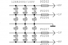
Agree the 100V jobs are quite a bargain compared to anything higher voltage. Did some checking on DigiKey and Mouser and the 200V parts you'd need to un-series the higher rail ones (connected to ground instead of the lower rails) are stupid-expensive even in the lower (not recommended) temperature.
The good thing is, though, instead of 3 x 8200uF, you'd only need 3 x 4100uF. You might even save money by going with 2 x 6000uF, or even 1 x 12000uF -- it's unlikely that somewhat worse ESR or other factors would be too detrimental.
Cheers
The good thing is, though, instead of 3 x 8200uF, you'd only need 3 x 4100uF. You might even save money by going with 2 x 6000uF, or even 1 x 12000uF -- it's unlikely that somewhat worse ESR or other factors would be too detrimental.
Cheers
Capacitance will not be affected
When two same caps are in series the rated voltage doubles but the capacitance value halves
Before reconnecting the amplifier, after the faulty capacitors have been replaced, I would check the rectifier diodes.
If it is an amplifier built with quality components, it cannot be ruled out that the diodes also have AC leakage.
Once I had a TV that let the 50 hz phase pass from the line to the cathode ray tube, the famous horizontal dark line that moved vertically ... I'm talking about the black and white era!
The rectifier diodes measured "good", that is, they conducted only one way, but they did not rectify AC enough, replacing them solved the fault.
Here is an attachment on how to do it, although it is in Spanish.
Como probar los diodos | Fluke.
(Sorry for the repetition -- I blew the 30-minute edit timeout (forgot and left a sauce pan on a malfunctioning burner -- phew-ee!)
Agree the 100V jobs are quite a bargain compared to anything higher voltage. Did some checking on DigiKey and Mouser and the 200V parts you'd need to un-series the higher rail ones (connected to ground instead of the lower rails) are stupid-expensive even in the lower (not recommended) temperature.
The good thing is, though, instead of 3 x 8200uF, you'd only need 3 x 4100uF. You might even save money by going with 2 x 6000uF, or even 1 x 12000uF -- it's unlikely that somewhat worse ESR or other factors would be too detrimental.
Putting them in series, unfortunately, halves the capacitance. You COULD put them in series if you return them to ground
Have you performed the experiment with smaller caps (whatever 100V units are on hand) unloaded, that was suggested earlier, just to see what actual voltages you have?
Cheers
From my reading the capacitance of series caps is equal to the smallest capacitance in the chain. Voltage across the caps is a function of capacitance of the caps relative to each other. My use case example the capacitance of two equal caps should be the same as for a single and voltage across each half of the total.
No its always smaller than the smallest in the chain. Its about adding reciprocals so say you put two 10000uF 100V caps in series you end up with one 5000uF 200V cap end to end. 1/Cs=1/C1+1/C2. Also keep in mind that when not equal uF due to tolerance and/or age, the smaller one will develop more voltage across it. The charge has to be the same since in series so the smaller capacity will stress to reach same charge you see.
Have you performed the experiment with smaller caps (whatever 100V units are on hand) unloaded, that was suggested earlier, just to see what actual voltages you have?
Cheers
Didn’t find suitable caps in the arsenal.
Yes, it is similar as two parallel resistors - where the total is always smaller than the smallest one.
And the DC voltage across series caps doe NOT divide by the cap ratio, but by the cap parallel (leakage) resistance. That is unpredictable, so people often use external resistors parallel to the caps to divide the DC voltage across the series caps.
In the current discussion where the voltage on the caps is externally defined, this is all moot of course ;-)
Jan
Its true that leakage resistance will be the main unequal voltage divider factor among otherwise equal electrolytic caps in series. Especially in very high voltage tube PSUs.
Kirchhoff stands despite of additional issues though. If there is appreciable difference in capacitance too, it will make things further unequal.
Lets use film caps in series as an example (which are mostly free of leakage) say 4.7uF and 10uF with 100V across the system. You will measure 68V on the 4.7uF and 32V on the 10uF. The small capacitance has to develop the more voltage to equal the charge of the big capacitance. Charge has to be the same on each cap in a series system because the electrons must flow at same quantity through each one cap.
............
If it is an amplifier built with LOW quality components, it cannot be ruled out that the diodes also have AC leakage.
...................
It went wrong here
- Home
- Amplifiers
- Power Supplies
- Inconsistent voltage after rectifier