Hello Friends,
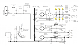
I've got a problem with an amp on my desk right now in that the power supply measures inconsisten voltage after rectification stage, see diagram.
The yellow highlighted caps are bulged and need to be replaced, though before I go to that expense, are the caps causing the voltage issue or must I look elsewhere?
As always, your help is hugely appreciated!
Attachments
Obviously...bad capacitors will cause that kind of problem.
And you need to replace them, before they do something bad, like exploding.
And you need to replace them, before they do something bad, like exploding.
Yes, given the state of this thing I'm pretty astonished it's not blown a gasket already. If nothing else is amiss, I'll go and replace the caps, which will cost about $100. I'm just not wanting to throw more money at this thing, in case there's a different fault at play.
Disconnect from circuit.
Remove caps
See AC voltage
Put small caps, see DC voltage.
If they are consistent, then only the caps are at fault.
If not, another fault besides the caps.
Small caps may be handy, and you need to check the no load voltage, to find the fault. Try 330 or even 2200, whatever is at hand, only one if more are in parallel, just need to check rectifier and transformer.
Check out the price for 4700, they may be much cheaper, put two in parallel.. or one each 4700 and 3300, that adds up to 8000, close enough.
Last edited:
Oh, and I put the circuit into a simulator, and it appears the DC voltages in theory would be 124 and 54. So looks like only the 121V is in the ballpark 🙁
125-0-125 is 250v across the transformer...
The other winding is 55-0-55, or 110 volts.
Check in the manual, could be the 55 v line also has faulty caps.
110 * 1.4 is 154, you are seeing 121 after faulty caps, it will be less than 154 due to capacitor smoothing.
Before diving in, get hold of the service manual...see what is expected, and also it could be a fault in the later regulation section.
And Denon use too many voltages, not satisfied like the others with only two, one about 12 for the pre amp, and a higher one for the power amp in Kenwood and Philips for example.
Their design seems to need more different voltages, making it more complicated than those of the others.
Anyway, see also why it came to you, the supplies you checked because of some fault, which you have not mentioned.
I mean, what made you open it to check?
Last edited:
The lower voltage and higher voltage capacitors are in series...high voltage rail to low voltage rail then to ground.
Peculiar
Please verify in manual and actual condition.
Peculiar
Please verify in manual and actual condition.
I got the amp as not working, my interest is to learn about them by pulling them apart and fixing them. The symptom is clipping lights are on and a loud 50hz tone through the speakers even with amp on minimum gain. Both stereo channels affected but less so in bridge mode, which may indicate phase reversal of the channels.
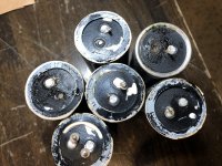
Pulled the bulged caps off and it’s not pretty. They were siliconed onto the board and some had leaked. It appears some of the connections were fouled through or at least the pins stayed on the board not on the caps. The caps also rattle when shaken. Is that normal?
Pulled the bulged caps off and it’s not pretty. They were siliconed onto the board and some had leaked. It appears some of the connections were fouled through or at least the pins stayed on the board not on the caps. The caps also rattle when shaken. Is that normal?
Attachments
Best way to learn about isnt to buy a broken one.
You need to learn circuit theory first.
Otherwise you are poking around in the dark.
Given you have an amp now get circuit diagrams and learn how it works from books.
I have been on the end of amateurs having had a go at fixing things and making it worse.
Bought in a Maplin disco amp. It had a lot of distortion.
I checked all components and they were fine and pcb had no breaks or bad joints.
Turned out someone had put in a npn transistor in place of a pnp.
The numbers had worn off so I couldnt see what they were.
It diode checked ok but was obviously wrong way around which I didnt check for to start with.
Those caps are badly damaged, should not rattle.
Can you post a photo of the top, so we can see the markings?
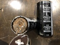
And it just could be that they are small caps inside big housings, a common trick in China, though in Western countries I can't say.
Try and cut one that is not foul smelling.
And like Nigel says, don't go doing things where you need to learn first.
I had a TV repairman put a NPN instead of PNP in the colour circuit, my regular repairman fixed it later, the colors were wrong and fuzzy. The regular guy was out of town, and I had taken the circuit to a man in the market to fix.
Among the reasons why I prefer to do this work myself.
Denon is complicated compared to others, and needs experience.
I have no idea about your level of experience and equipment, but my advice is to proceed carefully, lots of parts like output transistors are next to impossible to find, and so are some of the intermediate stage parts, and blowing them as part of experimenting is not going to help.
Can you post a photo of the top, so we can see the markings?
And it just could be that they are small caps inside big housings, a common trick in China, though in Western countries I can't say.
Try and cut one that is not foul smelling.
And like Nigel says, don't go doing things where you need to learn first.
I had a TV repairman put a NPN instead of PNP in the colour circuit, my regular repairman fixed it later, the colors were wrong and fuzzy. The regular guy was out of town, and I had taken the circuit to a man in the market to fix.
Among the reasons why I prefer to do this work myself.
Denon is complicated compared to others, and needs experience.
I have no idea about your level of experience and equipment, but my advice is to proceed carefully, lots of parts like output transistors are next to impossible to find, and so are some of the intermediate stage parts, and blowing them as part of experimenting is not going to help.
I somehow thought it is a Denon, can you give details of make and model?
The thought of Denon came because another one is in Hyderabad, with a blown channel, I am trying to help the owner fix it, two professionals refused to do it.
Like yours, it has many voltages coming from the power supply.
He tried, a capacitor exploded, now he is a little less confident.
He is professionally qualified in electronics, and wants to tread carefully. He is into IT, this is not really his area of expertise.
So please tread carefully.
Last edited:
Not really.Obviously...bad capacitors will cause that kind of problem.
It´s not a capacitor fault but wrong voltage used, dangerously tight specs.
They are the *victims* , not the murderer.
Cause and effect.
Top ones receive (125-55)Vac * 1.4142 so 70Vac * 1.4142=99Vdc , can´t survive normal mains voltage variations.
While bottom ones receive 55Vac * 1.4142=78Vdc , most reasonable.
Replacing is not enough, you must upgrade specs, to at least 120V ; 140V or 160V would be safer.And you need to replace them, before they do something bad, like exploding.
Using same voltage spec, even if from a "good brand" , will sooner or later repeat the problem.
I am waiting for him to tell us the brand and model.
As it is I think putting that kind of circuit with two sets of capacitors in series was peculiar, it is not as if higher voltage capacitors are not made. Should have used two sets, one for each voltage.
Thank you for pointing out that basic, and stupid, error in the design...it seems the original makers were not aware of the principle of margin of safety. Or did not care.
They may have been counting on a relatively high quiescent load to keep the outer rails within the capacitors' rating -- but yah, pretty foolish I agree!
Then, what if the load increases on the lower rails but not the upper? Open circuit voltage on the higher rail's caps already works out to 99V (unless I booted the arithmetic).
No wonder the poor things look like they've been to hell and back. Hope you didn't have to tear up the circuit board too much getting them out.
And for future reference, any time you encounter electrolytic capacitors that look like those -- they gotta go! 😀
Cheers
Last edited:
I opened a cap. It’s dry like the desert. The rattle was the tightly rolled wad of paper loose in the canister.
I ordered 12 replacements. I got 100v ones as anything else is prohibitively expensive. I understand that they will likely only last 10 or so years.
The amp is a Deton a.one which is the same as t.amp proline 3000. I’ve got the schematic. I uploaded it in my first post. Actually I found the schematic on this wondrous forum, so thanks again.
This is a simple and beautifully robust amp, picture the love child between a John Deere and a boat anchor, and just the right sort of kaputt that I don’t have to worry about the temp of the soldering iron when I work on it. It will be put into duty powering my 2 x 18” subs that are hanging off a rather anaemic 160w at the moment.
Long story short, this is not about being effective. Landfill is the only logical solution for this beast. I’m doing this for fun because I like it when things work out in the end 🙂
Attachments
Loud buzz = knackered caps.
Actually 100Hz as it's bridge rectified.
No, you wouldn't expect them to rattle.
And you are right, that much capacitance costs!
Actually 100Hz as it's bridge rectified.
No, you wouldn't expect them to rattle.
And you are right, that much capacitance costs!
- Home
- Amplifiers
- Power Supplies
- Inconsistent voltage after rectifier