2023 - okay, I really want to go through turntable circuit of my JVC (actually Victor) JL-B31 and fix the speed problem. This is something I posted about on and off last year on another forum, but I seem to have stalled with responses there. I'm hoping that someone has the patience to tell me what to test, and in some cases exactly how, right down to "put the -ve probe on A and the +ve probe on B"...Yep; I'm afraid there are many parts of the circuit/schematic I don't properly understand. I can post photos of anything that might help to clarify things.
I have the service manual, and have spent a lot of time gazing at the schematic and the components on the boards, without much in the way of enlightenment occurring. I've done some measurements but it clearly hasn't been enough to identify the problem. A quick summary:
Powered on, the platter rotates very slowly at first, picks up speed over about half a minute, and drifts back and forth between too fast and too slow. Top panel variable resistors don't stabilize it.
The switches, power cap and rectifier diodes all seemed to check okay, though I replaced a power cap anyway. I do need to measure the TO3 transistor, and I'm unsure/nervous about what to do there: it should be 75V, measuring the collector (metal case) and...where does the other probe go?
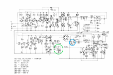
The replaced power cap is C822, which I've circled on the schematic (along with X814, the TO3 transistor I will need to measure). The other caps in the power supply I left alone. In the end, out of a faint hope that it might make some difference, I replaced the electrolytics, as there are only about a dozen. But much as I expected, that's not where the problem is.
Any suggestions about what to look for start with this? The motor is clean and lubed and there are no obvious signs of issues originating there.
I have the service manual, and have spent a lot of time gazing at the schematic and the components on the boards, without much in the way of enlightenment occurring. I've done some measurements but it clearly hasn't been enough to identify the problem. A quick summary:
Powered on, the platter rotates very slowly at first, picks up speed over about half a minute, and drifts back and forth between too fast and too slow. Top panel variable resistors don't stabilize it.
The switches, power cap and rectifier diodes all seemed to check okay, though I replaced a power cap anyway. I do need to measure the TO3 transistor, and I'm unsure/nervous about what to do there: it should be 75V, measuring the collector (metal case) and...where does the other probe go?
The replaced power cap is C822, which I've circled on the schematic (along with X814, the TO3 transistor I will need to measure). The other caps in the power supply I left alone. In the end, out of a faint hope that it might make some difference, I replaced the electrolytics, as there are only about a dozen. But much as I expected, that's not where the problem is.
Any suggestions about what to look for start with this? The motor is clean and lubed and there are no obvious signs of issues originating there.
Attachments
Last edited:

These 'analogue' type speed circuits are hugely complex. I doubt the T03 transistor is faulty.
All the small electrolytic caps are going to be pretty critical but if you've replaced them all...
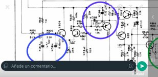
Check the 470k near the circled power transistor. It has that 'look' of a stressed location. High voltage and all that.
Make sure the 15v rail is clean and stable. Beyond that I would use a scope to look at the two inputs to the circuit from the platter (top left) and check the output on the collector of those two first transistors.
All the small electrolytic caps are going to be pretty critical but if you've replaced them all...
Check the 470k near the circled power transistor. It has that 'look' of a stressed location. High voltage and all that.
Make sure the 15v rail is clean and stable. Beyond that I would use a scope to look at the two inputs to the circuit from the platter (top left) and check the output on the collector of those two first transistors.
I circled the resistor you mentioned on the board layout: R846. Do I just measure in circuit (power off) from the underside of the board? All I got from the top was 0.003 at the 2M setting.

In the past, I was able to stably get 15V - I think I had to adjust a VR to set that, so as that might have been shifted by me since, I'll have to go back and recheck that.
For testing, I have just used a multimeter in the past. I have an analogue scope, but other than switching it on and randomly doing a few things with it to get a rough idea of what it does (and in the interval since, forgetting a lot of it) I haven't used it for any real world testing, and don't really know much about using them.
For testing, I have just used a multimeter in the past. I have an analogue scope, but other than switching it on and randomly doing a few things with it to get a rough idea of what it does (and in the interval since, forgetting a lot of it) I haven't used it for any real world testing, and don't really know much about using them.
The scope essentially shows voltage against time. Looking and comparing those two inputs from the rotating platter would be a start. We don't know exact values but I would think each one should be similar amplitude, most like a sine wave and perhaps of a couple of volts peak to peak.
It's not an easy circuit to be learning on, I'll fully admit that. Analogue 'servo' type circuits like these are quite critical on everything being correct.
It's not an easy circuit to be learning on, I'll fully admit that. Analogue 'servo' type circuits like these are quite critical on everything being correct.
Useful to know that it's a complex circuit. I had assumed it was simple based on the fairly low number of components on the board, but for anything beyond the most basic circuits, I can't easily see what's going on or how complicated they may be. My main experience is building a few tube amp kits, but those came with step by step instructions and a handholding approach to the measurement/testing workflow.
I'll get the scope out at some point and see what it can show me. I'd need some help on that too though. Most of this I will only be able to make time for at the weekends. I'm a little wary of getting into anything more taxing/safety-crucial than soldering after a day at work. But I do believe this table must be repairable, and I hope to learn something from it along the way.
I'll get the scope out at some point and see what it can show me. I'd need some help on that too though. Most of this I will only be able to make time for at the weekends. I'm a little wary of getting into anything more taxing/safety-crucial than soldering after a day at work. But I do believe this table must be repairable, and I hope to learn something from it along the way.
If the speed of the table is irregular, thus the servo circuit is oscillating at a low frequency. At first, try loading it with a heavy weight (two or three beer cans filled dispossed symmetricaly around its center). This will increase looses, and see if speed tends to stabilize (this is not a solution, is a kind of test only). After it, increase damping trying to brake it with your fingers, for example.
Check speed sensor is OK. If it is optical, clean led and phototransistor with a clean swab or brush wet with isoprophyl alcohol. If it is magnetic, the same but also check the magnet isn't filled with iron particles disturbing magnetic field. Also verify lubrifing of the gearing, bearings, etc. If it is belt drive, check or replace it.
Keep us posted.
Thanks. I will, though I won't be able to get to this again for a few days. I think the speed sensor would have to be the magnet in this illustration:

Perhaps there is a hall effect or more around the inner motor diameter. Can you see them?
Also try shorting briefly the c-e junction of the to3 transistor and see if the motor is capable of reach full speed witouth issues.
Also try shorting briefly the c-e junction of the to3 transistor and see if the motor is capable of reach full speed witouth issues.
Not sure what you mean about the motor. I haven't had that section open in months, but I recall there was a trace pattern arranged in a circle on the circuit board there, is that what you're referring to? I made sure at the time that that board was clean and there was no obvious evidence of damage to the trace. It looked fine.
Also, I'm not sure what the magnet at 9 is designed to do, there's no obvious design on the underside of the platter. The two holes pass to the inside and as the rim of those holes is lower than the flat underside of the platter by a few mm, maybe they block the field as they pass the magnet?
If you've seen the service manual, which is very brief, it doesn't give much detail about any of that - no description of the principle of operation, or how the motor control works. The magnet is simply shown in the illustration and numbered in the parts list.
Unfortunately, I have to leave this for a day or two, my holiday ends this evening but I'll try to get back to it this weekend, in light of what's been suggested in this thread so far. Thanks everyone, I really appreciate the help.
Last edited:
Now I undestand. The circuit is quite simple in theory.
The zig zag track is an inductance that is scanned by the magnetic field of the rotor. At pic #1, pin #3 and #4 you obtain a tachometric frequency and voltage proportional to motor speed. The upper side transistors Q601 to Q606 make the waveform very square, limiting, amplifying it to reach certain voltage level. D802 and D803 rectify this wave and Q607 and Q608 are a monostable whose duty is proportional to speed. Now in the lower side of the schematic, this mono's pulses are filtered to obtain a DC (roughly filtered) by low pass filter Q611 and passive components around it. A voltage reference is created in its emmiter by Q816 and surrounding components. The difference at its collector is amplified in current to drive final transistor Q813/14 acting as AC variable resistance.
Thus viewing in detail, my attention would be focused to the low pass filter. Perhaps those 'lytics are dry or leacky and its behaviour is wrong.
If for any reason the time constant of the filter became too long, when starting the motor, the loop signal is null and the output to drive the motor is at maximum. Approaching desired speed, the signal must be reduced. But this action is too late, so the motor acquires too high speed. Thus, the loop "takes into account" that the speed is too high, thus reduces driving to the motor. Again, the reduction appears too late and motor reduces its speed to a too low value and so. This cycle repeats itself at the lower time constant of the system, usually mechanical motor+plate mass/friction/inertia time function.
Is this a "hot chassis" device? No galvanic isolation from the line?
- Home
- Source & Line
- Analogue Source
- Inconsistent speed: JVC JL-B31