I agree with all the previous posts on how dipoles work and our perception, all to be found in Linkwitz's writings I believe? Can we get back to the task in hand? 😉 Pairs of reversed drivers still seems good to me although few have shown much interest....🙂
Two measurements demonstrating the effect of a baffle on the directivity (360 degrees horizontal, normalised) of a small driver (Vifa TC9FD18-08). On the left is the naked driver, on the right the same driver center mounted on a 36cm wide and 57cm high baffle.


Notice how the baffle increases the dispersion in the range between 1kHz and ~3kHz, exactly the range where our ears are most sensitive.
Here's a measurement of the directivity of the Linkwitz Orion (180 degrees horizontal, normalised):

This measurement only shows the frontal directivity but a similar increase in dispersion can be seen here.
Notice how the baffle increases the dispersion in the range between 1kHz and ~3kHz, exactly the range where our ears are most sensitive.
Here's a measurement of the directivity of the Linkwitz Orion (180 degrees horizontal, normalised):
This measurement only shows the frontal directivity but a similar increase in dispersion can be seen here.
I agree with all the previous posts on how dipoles work and our perception, all to be found in Linkwitz's writings I believe? Can we get back to the task in hand? 😉 Pairs of reversed drivers still seems good to me although few have shown much interest....🙂
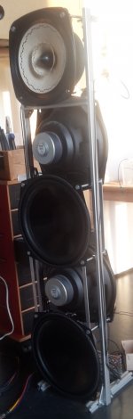
I use reversed drivers in my other speaker: 4x WS25e per side (a high QTS 10" woofer with 5.5mm xmax). I did it mostly because:
- I wanted to keep a narrow baffle (Gerrit Boers thread explains why) but have as much cone surface as possible below the Fostex widerange at eir height. This way I was able to fit 4 instead of 3.
- I am also lazy, so attaching them with some bolts and alu strips is faster than woodworking;
- And indeed, maybe the distortion is also less and the dipole figure more constant - I have not measured.
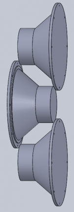
I am still thinking about doing something similar with the new speakers using the SB34NRX75-16: I could fit three below the midrange and tweeter. The sketch shows it, the total height would be 80cm, so still enough space on top for mid and tweeter. Thinking further, this could turn into a 4 way, add some wings, the two lowest SB12s playing up to 100Hz, the top another 2 octaves... and a new project is born 🙂
Attachments
I agree with all the previous posts on how dipoles work and our perception, all to be found in Linkwitz's writings I believe? Can we get back to the task in hand? 😉 Pairs of reversed drivers still seems good to me although few have shown much interest....🙂
A pair of drivers, one reversed, just does not work all that well as a dipole except at "lower" frequencies where the wavelength >> front-to-back separation. At lower frequencies it's fine and may even have some advantages, but is just a more complicated solution to dipole radiation in that band compared to a single driver.
Returning to the thread topic:
To me, the challenges in dipole design are in the higher frequencies, e.g. 1kHz and above. If the goal is to have both smooth and CD-like on and off axis response, and identical front-back radiation pattern, the separation of the loudspeaker bands into <2kHz and >2kHz seems to naturally follow. Then the task is finding a driver that is dipolar in these bands, e.g. midrange and tweeter. From my measurements a moving coil driver can cover up to 2kHz most easily and practically, with the Neo10 (NLA?) planar one exception. The >2kHz band is most easily handled by a dipole ribbon tweeter, but other solutions might exist.
Once those two bands have been ironed out, it remains for the designer to fill in the lower bands. The choice of how many is a matter of the construction choices (baffled, unbaffled) and how high in SPL the system must play. If the midrange can play down to 600Hz, it is possible to have only one band below that frequency however it cannot have a very large front-to-back distance and therefore will not have much output capability below about 80-100Hz. Adding one more band, allows a driver to cover 100-600Hz with high output large pro woofer using very little baffle (to keep the radiation patterns clean) and then a "dipole subwoofer" is used below 80-100Hz. The sub can be designed to have as large a front-to-back pathlength as possible, which will provide as much low frequency output capability as possible.
The concepts described above explain how I am currently approaching system design and why.
Last edited:
Let me guess....."best bass ever!!" ....
Of course Scott, why go for less than the "best bass ever"?
Shallow 6 dB rolloff is easy to equalize, at least in active setup.
However, impedance peak is very steep in most cases...
Maybe it could be possible to see also the low end as challenging for that reason.
The amplifier should have low output impedance and sufficient heat dissipation ability.
I did not check in practice whether the amplifier with small heat sinks could be overloaded, but on the slopes of steep impedance peak a lot of reactive power can be generated (in theory).
OK, but how is this any different than in other (sub) woofers? Am I missing some point that was not explicitly stated?
Because the resonance frequency of a driver in a dipole type system is lower than when the same driver is loaded by a box, I would expect any issues with the reactive load to be less problematic for the dipole system...
Because the resonance frequency of a driver in a dipole type system is lower than when the same driver is loaded by a box, I would expect any issues with the reactive load to be less problematic for the dipole system...
You're right to say that, but adding to Charlielaub's post, the sound output when connected to an amp is nothing as tall and narrow as the sharp impedance curve. And that is rather different than the perceived loudness.However, impedance peak is very steep in most cases...
And if you look closely at the "sharp" curve, it may really end up giving a very welcome boost in an OB half an octave wide or more.
I found using a driver with a low resonance quite satisfactory.*
B.
* when I was a kid, we looked for drivers with Fo approaching 20 Hz. For various reasons such as the urge to have great power handling, that's not in the cards today and builders routinely accept far higher resonances that fall into the desired passband. Bad move.
Last edited:
Shallow 6 dB rolloff is easy to equalize, at least in active setup.
However, impedance peak is very steep in most cases...
Maybe it could be possible to see also the low end as challenging for that reason.
The amplifier should have low output impedance and sufficient heat dissipation ability.
I did not check in practice whether the amplifier with small heat sinks could be overloaded, but on the slopes of steep impedance peak a lot of reactive power can be generated (in theory).
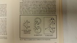
You bring up a great point for discussion, here. For essentially free-air mounting of any given woofer driver, sure enough, the resonance point is not raised much, if any at all. Place it in an enclosure and sure enough, it will be raised in frequency along with the same ratio as the Q is raised. *At the same time*, the amplitude of resonance is diminished by quite a bit, in an enclosure, yet this *does not happen* in free air. Thus, as impedance grows, power goes. There has been much discussion with regards to this situation, and how the amplifier sees it. Is less power demanded because of the impedance peak, or is less power possible, because of the impedance peak (??)
From an old text book
From an old text book. I know, I know, fact based information from a text book, could possibly be frowned upon, in some circles.
Of course Scott, why go for less than the "best bass ever"?
From an old text book. I know, I know, fact based information from a text book, could possibly be frowned upon, in some circles.
Attachments
I think you mean the impedance maximum... and you are correct. BUT in a closed box the loudspeaker is typically used THROUGH the resonance region, so the amp will see all of the peak. In contrast in a dipole sub the loudspeaker is being used primarily ABOVE the resonance region, so the amp is mostly working on the capacitive side of the peak. Anyway, is this really any kind of problem at all? If it gets your panties in a bunch, add a 22R 100W power resistor in parallel with the loudspeaker to drop the Zpeak. It's completely unwarranted, but if you wanna do it I won't stop you.*At the same time*, the amplitude of resonance is diminished by quite a bit
When the impedance is high, there is less power delivered to the load. But the driver is at resonance, and so it more efficient at converting energy input to acoustic output compared to frequencies away from resonance.Is less power demanded because of the impedance peak, or is less power possible, because of the impedance peak (??)
The "problem" around resonance is that the driver is not acting like a resistor but more like a capacitor or inductor (on each side of the peak) and this causes it to give and take the power from the amp differently. It's not as easy to drive this kind of load compared to a purely resistive one, but it is something that amplifiers deal with all the time.
It is easier for the amp to drive a load that is not both very low impedance (e.g. Re=2 Ohms) that is also highly reactive (strongly capacitive or inductive).
Here is an article about this subject that might be of interest to you, and talks about how different types of amplifiers handle reactive loads:
Phase Angle Vs. Transistor Dissipation
Another thing to point out is this is only a problem around resonance. The only driver in a dipole system that will be operated around its resonance frequency is the lowest band, e.g. the woofer or subwoofer. All other drivers are operated away from (above) resonance and this is a moot point for them.
Last edited:
I think you mean the impedance maximum... and you are correct. BUT in a closed box the loudspeaker is typically used THROUGH the resonance region, so the amp will see all of the peak. In contrast in a dipole sub the loudspeaker is being used primarily ABOVE the resonance region, so the amp is mostly working on the capacitive side of the peak. Anyway, is this really any kind of problem at all? If it gets your panties in a bunch, add a 22R 100W power resistor in parallel with the loudspeaker to drop the Zpeak. It's completely unwarranted, but if you wanna do it I won't stop you.
Here is an article about this subject that might be of interest to you, and talks about how different types of amplifiers handle reactive loads:
Phase Angle Vs. Transistor Dissipation
Sorry, I did not mean to offend you. Just stated another aspect of enclosure loading. My panties are not bunched up, and Thanks, Kindly, for the article.
No, no, no... Not offended - that's just my sense of humor! It was not meant for you or anyone in particular.
I actually did that (added a bunch of power resistors in parallel with the driver) in an old PR subwoofer project that I built many years ago to reduce the twin impedance peaks. See attached pic during construction. Used two TC Sounds 12" subs plus an 18" PR.
I actually did that (added a bunch of power resistors in parallel with the driver) in an old PR subwoofer project that I built many years ago to reduce the twin impedance peaks. See attached pic during construction. Used two TC Sounds 12" subs plus an 18" PR.
Attachments

A wide and high impedance peak is a result of strong motor which will induce a lot of microphonic "back-EMF". The height is determined by the mechanical losses.You bring up a great point for discussion, here. For essentially free-air mounting of any given woofer driver, sure enough, the resonance point is not raised much, if any at all. Place it in an enclosure and sure enough, it will be raised in frequency along with the same ratio as the Q is raised. *At the same time*, the amplitude of resonance is diminished by quite a bit, in an enclosure, yet this *does not happen* in free air. Thus, as impedance grows, power goes. There has been much discussion with regards to this situation, and how the amplifier sees it. Is less power demanded because of the impedance peak, or is less power possible, because of the impedance peak (??)
For the transducer efficiency (acoustic vs dissipated power) a beefy, low Qes motor is best, combined with soft spider/air spring (which becomes dominant below Fs). While with an electrically overdamped (eg, Qes=0.2) the voltage the amp must develop to "overcome" the back-EMF voltage is high, the current needed to control the driver is low, the stronger the motor the lower it is, and lowest around resonance.
This very reactive nature of the impedance can be a problem for power dissipation of linear amps, but PWM amps and concepts with switched or PWM-tracked supply rails have zero problem with it (PWM actually shifts the reactive current back into the rails).
Of course the SPL target can only be achieved by heavy EQing, but there is only a voltage/headroom penalty but no efficience issue with a pronounced impedance from a strong low Qes high Qms woofer, peferably one with a low Fs. Low Qes drivers (wide and high impedance peak) are pretty much self-controlled by VC velocity around resonance and that helps precision big time compared to a typical dipole woofer with a intentionally weak motor in order to achieve a high (0.7ish) system Q to avoid EQing... a wrong route in my view, a dead end, at least whithin an active concept, notably with PWM amps on the bass channel.
An exception is when the system is undersized and the woofer is prone to exceed Xmax often. Then the low-Qes woofers fall apart much uglier than the dipole specialist. But that can be fixed, emulate the proper output impedance that gives best balance between general precision and overload behavior and recovery from it.
How about the old trick of adding mass of woofer cone? It lowers Fs but what else?
A dipole woofer don't have to go very high in a 4-way system.
With dsp and modern HO classD amps this is deceivingly easy to handle, at the expense of high distortion and breaking the driver.
A dipole woofer don't have to go very high in a 4-way system.
With dsp and modern HO classD amps this is deceivingly easy to handle, at the expense of high distortion and breaking the driver.
it kills me when people discuss speaker design for bass performance with no reference to any particular room, and the problem really starts and ends with the room. To start conceiving the problem those are well advised to use an online room resonance calculator and simply count the number of acoustic modes calculated, (including the oblique reflections).
that is why there is no "one size fits all" design solution, only a preference at a particular listening position in a particular room with a particular speaker placement and while listening to a particular music material.
I enjoy when I come across a comment from a speaker designer reiterating the same. For example Jeff Bagby over at techtalk was saying how it never failed to surprise him how different a speaker which he had designed for his room could sound at another guy's place, because of the bass being different and then everything else being subjectively referenced to that bass.
I attached here some starters for a serious discussion.
also multi-amped setups with digital Xovers and EQ do not have to deal with ridiculous physical constraints for equal passive outputs. So the design goal should clearly state one or the other. So we do not have to deal with questions: "How big does it have to be to get this low at this level of output ..etc". Moreover I prefer multi-amped setup because I can take it further and also match sonic qualities of amps and speaker drivers and get the best bottom, best mid and best high performance. just my 2 cents..
Attachments
Addendum: ScottL's last question could also refer to a sound quality impedement for the amp when it has to handle high reactive behaviour, maybe I got that wrong in the previous post.
For a modern high feedback design, PWM especially, I don't see any problems if they a genereously sized but for open-loop linear-type amps the higher crest factor of current (transient vs. steady-state) may cause additional coloration, besides the thermal issues. So I think we can claim with typical music material operation around Fs especially with a high and wide impedance peak will tackle the amp more than driving an ohmic load even when this a much lower value.
For a modern high feedback design, PWM especially, I don't see any problems if they a genereously sized but for open-loop linear-type amps the higher crest factor of current (transient vs. steady-state) may cause additional coloration, besides the thermal issues. So I think we can claim with typical music material operation around Fs especially with a high and wide impedance peak will tackle the amp more than driving an ohmic load even when this a much lower value.
Please clarify the back emf
I have never understood how to calculate how much back EMF affects drivers....Please advise the method or calculation to derive an actual quantifiable figure Ie If 100 watts( or joules of energy if this makes it easier?)of power is going into the driver what percentage of that power is generated by the river as back EMF?
What really concerns me is that if we have a good old fashioned 1 bar (1Kw) electric fire sitting on the lounge floor, and next to it a 21 inch pro sub woofer with 1kw AES continuous power handling they both convert approx 97% of the electrical energy into heat..... But we do not classify the electric heater as "electro dynamic motor"....
Maybe my question is really what percentage of the tiny percentage of electrical energy the driver converts to sound is used to generate back EMF?
Thanks in advance
Cheers
A.
A wide and high impedance peak is a result of strong motor which will induce a lot of microphonic "back-EMF". The height is determined by the mechanical losses.
I have never understood how to calculate how much back EMF affects drivers....Please advise the method or calculation to derive an actual quantifiable figure Ie If 100 watts( or joules of energy if this makes it easier?)of power is going into the driver what percentage of that power is generated by the river as back EMF?
What really concerns me is that if we have a good old fashioned 1 bar (1Kw) electric fire sitting on the lounge floor, and next to it a 21 inch pro sub woofer with 1kw AES continuous power handling they both convert approx 97% of the electrical energy into heat..... But we do not classify the electric heater as "electro dynamic motor"....
Maybe my question is really what percentage of the tiny percentage of electrical energy the driver converts to sound is used to generate back EMF?
Thanks in advance
Cheers
A.
I have built many prototype U, H, W, M baffles and the vibration is always a problem
IMO best solution for OB bass is a nearfield ripole sub (vibrations cancelled)
i would suggest using 2x high-eff pro 18" for the ripole sub
if such a nearfield ripole sub is not possible (WAF etc.) and the main speakers have to be somewhat close to the front wall then i suggest cardioid bass
if done right, deep OB bass feels like gravitational waves coming from below... the room disappears
- Home
- Loudspeakers
- Multi-Way
- In Pursuit of a 20-20k Dipole Loudspeaker