Having Problems
I have just plugged in my first ever LM3886 amp a la Carlosfm'
s design: but no sound ... just -2.0V DC output and no AC voltage (both measured using a multi-meter and some test tones.)
My first question ... do you need V+ power to both PINS 1 and 5? I notice that they do not test as being the same pin (using the little continuity meter - even on an unopenned LM3886), and I have only connected power to pin 5.
Because I am not using a pre-amp, I have increased the gain using a 40 ohm resistor to ground in the feedback loopjust to make sure my board works.
I am pretty confident that things which are supposed to contact do, and those which are NOt supposed to contact don't.
My next little project will be to submit my circuit board for you to check, because I am going stupid checking and rechecking. But I guess that is the joy of DIY 🙁
Regards,
George.
PS I am sure that the power supply is producing the right voltages ... they all check out nicely.
Re: Having Problems
If you used a 40R resistor to ground and kept the feedback resistor of 2k as in Carlos' schematic, you are running the amp with a gain of 51. I am not sure if this is within the specified limits, so my suggestion is to change it to 100R first and see if that works.
Mick
GeorgeBoles said:I have just plugged in my first ever LM3886 amp a la Carlosfm'
s design: but no sound ... just -2.0V DC output and no AC voltage (both measured using a multi-meter and some test tones.)
My first question ... do you need V+ power to both PINS 1 and 5? I notice that they do not test as being the same pin (using the little continuity meter - even on an unopenned LM3886), and I have only connected power to pin 5.
Because I am not using a pre-amp, I have increased the gain using a 40 ohm resistor to ground in the feedback loopjust to make sure my board works.
I am pretty confident that things which are supposed to contact do, and those which are NOt supposed to contact don't.
My next little project will be to submit my circuit board for you to check, because I am going stupid checking and rechecking. But I guess that is the joy of DIY 🙁
Regards,
George.
PS I am sure that the power supply is producing the right voltages ... they all check out nicely.
If you used a 40R resistor to ground and kept the feedback resistor of 2k as in Carlos' schematic, you are running the amp with a gain of 51. I am not sure if this is within the specified limits, so my suggestion is to change it to 100R first and see if that works.
Mick
Re: Having Problems
Here's the problem.
Connect the positive voltage to pins 1 and 5
GeorgeBoles said:My first question ... do you need V+ power to both PINS 1 and 5? I notice that they do not test as being the same pin (using the little continuity meter - even on an unopenned LM3886), and I have only connected power to pin 5.
Here's the problem.
Connect the positive voltage to pins 1 and 5
With thanks
Thanks Carlosfm, Nuuk and Mike_F.
I had put a little jumper from pin 1 to 5 "just in case" before I wrote my letter for help, but have not checked that it all works as yet. However, given your advice Carlos, I am a much happier man today and I expect everything to be fine. "No power = No go!" (I always thought it a bit odd that pins 1 and 5 never tested as being in continuity. What an odd situation!)
Nuuk, I've got to make eight of these beasties and my hand is not really steady and my eyes strain more as the years advance, so I am trying the PCB for the time being. I expect to fiddle quite a bit (for fun) with these boards ... change the resistor type, add and change capacitors (all the usual DIY fiddles which I have never been able to play with before), and also change the gain once I get a pre-amp up and going, so I thought that PCB might be easier in that respect. I do admire the P2P style of the gain-clones though!
Mark_F, I was just trying this board out as a prototype without a pre-amp, so I increased the gain so that hopefully I could hear something! I will change it back once a pre-amp is up and going. My first DIY power amplifier project (subwoofer and crossover)stalled for 18 months because I got no sound ... I didn't realize that the crossover board actually had some quite important gain!!)
Will let you know how it goes, hopefully tonight!!
Cheers to you all!
George
snubbers
Hello again Carlos.
Just a quick quetion for my education:
Does it matter which way round the snubber goes C-R or R-C in any particular situation? I imagine that it wouldn't, but I could be imagining incorrectly!
Regards,
George.
Hello again Carlos.
Just a quick quetion for my education:
Does it matter which way round the snubber goes C-R or R-C in any particular situation? I imagine that it wouldn't, but I could be imagining incorrectly!
Regards,
George.
Re: snubbers
George, it doesn't make difference, either way.
I use the cap to ground, anyway.
Just like on my avatar. 😀
GeorgeBoles said:Hello again Carlos.
Just a quick quetion for my education:
Does it matter which way round the snubber goes C-R or R-C in any particular situation? I imagine that it wouldn't, but I could be imagining incorrectly!
Regards,
George.
George, it doesn't make difference, either way.
I use the cap to ground, anyway.
Just like on my avatar. 😀
Re: With thanks
Probably one of the internal seccions of the chip is fed from one of the positive voltage pins (1 or 5) independently.
GeorgeBoles said:"No power = No go!" (I always thought it a bit odd that pins 1 and 5 never tested as being in continuity. What an odd situation!)
Probably one of the internal seccions of the chip is fed from one of the positive voltage pins (1 or 5) independently.
We have lift-off
Dear Carlos,
We have sound, (gain of 50 still not quite enough, though - awaiting pre-amp) with thanks to you without having to waste time re-testing everything.
At present, it sounds clean and satisfactory (2000uF filter capacitors at V+ and V-), but I am sure will be much better with your snubber recipe and some high quality bypass capacitors on Cin.
Regards,
George.
Re: We have lift-off
George, a gain of 50 is way too much, you can use it for now, but a good preamp and a gain of around 20x on the amp will sound much better.
Later, then.
GeorgeBoles said:Dear Carlos,
We have sound, (gain of 50 still not quite enough, though - awaiting pre-amp) with thanks to you without having to waste time re-testing everything.
At present, it sounds clean and satisfactory (2000uF filter capacitors at V+ and V-), but I am sure will be much better with your snubber recipe and some high quality bypass capacitors on Cin.
Regards,
George.
George, a gain of 50 is way too much, you can use it for now, but a good preamp and a gain of around 20x on the amp will sound much better.
Later, then.
Carlos, are there pdf files of your amp and psu? You know those with the tracks in them. I am sorry, I am at sea if I try to decipher the single line schematics.  I tried a search and couldn't find any. Most interested to try your amp out and if I have those, I'll be able to try and build my own boards.
Thanks and a Merry Cristmas and a Happy New Year too to all.
Regards.
I tried a search and couldn't find any. Most interested to try your amp out and if I have those, I'll be able to try and build my own boards.Thanks and a Merry Cristmas and a Happy New Year too to all.
Regards.
Shehzad, I didn't make a PCB (yet...) for this last version of the amp, and even for the PSU.
I would like to have more time for all this, but I don't...
You can easily implement my amp/PSU on a BrianGT / Peter Daniel kit.
I have made several PCBs, including this 'old' inverting PCB I made a few years ago, which I will sometime update for non-inverting, bigger PSU caps on the chips, and snubberized.
The beauty of this is that it can be used with a common or independent PSU per channel.
Howzat? 😎
Attachments
Carlos, thanks for the file. I'll get some of my more knowledgable friends to help me. Ever since I manage to complete my first DIY and GC project, the bug is biting. 😀 The GC is off a board I received as a present from a friend who visited China and bought it for me. It's running off a standard bridge rectifier, and from the posts I have read, your PSU seems to wonders for the GC. I would love to be able to access all the projects I wanna do, but I guess I just have to learn some patience and rein in my enthusiasm. 😀 It's a case of so many GCs you wanna build but nit enough time or resources. 😀 Definitely wanna have a go at your PSU and see how it wil remake my GC.
Thanks again.
Thanks again.
And just to confirm, the latest a greatest amp and power supply schematic versions from Carlos are:
Non-Inverting LM3886 amp version 4
and
Unregulated PSU Mkiv SE rev3
Correct?
Non-Inverting LM3886 amp version 4
and
Unregulated PSU Mkiv SE rev3
Correct?
Thank you Carlos. And in your setup you also use a preamp (rather than having a pot or attenuator on the amplifier itself) - with the most recent version of the schematic being:
AD815 Preamp Rev1 ?
I will have some Christmas-time projects to complete and want to make sure I am working on the most recent drafts 🙂
Cheers,
tm
AD815 Preamp Rev1 ?
I will have some Christmas-time projects to complete and want to make sure I am working on the most recent drafts 🙂
Cheers,
tm
idiotcountry2 said:Thank you Carlos. And in your setup you also use a preamp (rather than having a pot or attenuator on the amplifier itself) - with the most recent version of the schematic being:
AD815 Preamp Rev1 ?
Yes, that's it.
Oscillating I think!!
Hello everyone,
Well, I didn't think it possible, but I have managed to make an unreliable oscillator using LM3886.
Fundamentally, I have used CarlosFM's latest version circuit (the one with NO output resistors, a 3.3uF capacitor between + and - rails, and 0.1R resistors in the snubbers) with:
1) 2.2uF input capacitor (MKP style approx 200V unfortunately ... big ugly thing);
2) No bypass capacitors in parallel with it as yet;
3) 2000uF (>35V) electrolytics on + and - rail;
4) These capacitors NOT bypassed or snubberized as yet;
5) 2.2uF rather than 3.3uF capacitor from + to - rail, (63V Metallized Polyester MMK ... all I could get)
6) 330pF polystyrene across + and - inputs;
Unregulated power supply;
1) 80000uF + 2 * 4700uF WITH snubbers and bleed resistors as on most recent diagram;
2) 28.2V + and - rails (measure exactly and equal)
3) $2 bridge recitifiers * 2
4) 0.3 C/W heatsink (big enough for more than 4 of these amplifiers); white heat sink goop; LM3886TF style ICs (so shorts to heatsink not a problem;
5) 100k linear pot used as a volume control (variable resistance to ground) not just as a variable resistor;
(Is this right?? Could this be the problem, either the value or the arrangement of the pot???)
The source signal is my CD player, playing some test tones I recorded (only up to 200 Hz, though).
Speakers:
Nominal 8 ohm JBL's 25 years old. New superjunky tweeters ($2 each at Jaycar) also nominally 8 ohm. These work OK on my other amplifier (they don't sound too good, but for $2 what would you expect.)
Problems:
1. Quite high offset ... starts at about 1.5 volts and then slowly reduces a few minutes after startup to < 0.5 volts, perhaps lower.
2. Oscillation:
At various settings of this potentiometer, there will either be NORMAL function of the amplifier OR oscillation. (I say, "at various settings", because the amplifier appears to work apparently normally at very low levels, and at moderate and moderately high levels.)
The oscillation shows as:
a) The chip becomes VERY hot very quickly. (During normal function it is quite cool.)
b) Funny trace on oscilloscope which resolves to approximately one cycle per 4 microsecond (250 000Hz), when expanded.
There appears to be NO oscillation when the amplifier is not driving speakers but just the oscilloscope, however, the negative portion of the waveform is slightly flat a broad at its peak compared with the positive portion.
A bit more history:
I built a nearly identical amplifier (only difference being a minimally different circuit board), but reduced the resistor to ground to increase the gain to about 50. The circuit board was ever so slightly different to the current one. This worked absolutely FINE for more than an hour with the SAME POWER SUPPLY AND THE SAME SPEAKER. (Without snubbers and bypass capacitors it sounded a bit dead, but that is what I expected.) I then changed the gain by installing the the normal resistor to ground as in Carlos' diagram and got the SAME oscillations and high temperatures as I outlined above. It did this both WITH and WITHOUT a quick pre-amp (Pass NS10 Clone) I built. (I haven't bothered checking my current amplifier version with the pre-amp. I am a too despondent.)
With a multimeter, all the things which should be connected appear to be and there appears to be no cross connections/short circuits. For once, I am actually quite pleased with my soldering too!
Given that I am totally new at this:
1) Is my diagnosis of oscillation correct?
2) Would someone please review my PCB layout? Have I got the connections to the LM3886 correct? I have the capacitor's polarity as on my PCB diagram. I hope that is correct. Please confirm for me.
3) Is it the potentiometer value/arrangement causing the problems?
4) I hope it isn't likely to be the speakers, because it would be a pain trying to work out their impedance 🙁
5) Have I done something else dumb?
6) Where do I go from here? Add the snubbers? Change values?
All thoughts humbly received.
Regards,
George.
PS I have put the supply capacitors and C6 under the circuit board so that I can fix the LM3886's to the heatsink using a U-shaped piece of metal screwed at each end ... fewer holes in the heatsink so I can use it again if all this doesn't work!!
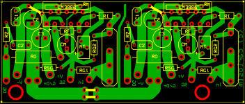
Here is the PCB Bottom
Hello everyone,
Well, I didn't think it possible, but I have managed to make an unreliable oscillator using LM3886.
Fundamentally, I have used CarlosFM's latest version circuit (the one with NO output resistors, a 3.3uF capacitor between + and - rails, and 0.1R resistors in the snubbers) with:
1) 2.2uF input capacitor (MKP style approx 200V unfortunately ... big ugly thing);
2) No bypass capacitors in parallel with it as yet;
3) 2000uF (>35V) electrolytics on + and - rail;
4) These capacitors NOT bypassed or snubberized as yet;
5) 2.2uF rather than 3.3uF capacitor from + to - rail, (63V Metallized Polyester MMK ... all I could get)
6) 330pF polystyrene across + and - inputs;
Unregulated power supply;
1) 80000uF + 2 * 4700uF WITH snubbers and bleed resistors as on most recent diagram;
2) 28.2V + and - rails (measure exactly and equal)
3) $2 bridge recitifiers * 2
4) 0.3 C/W heatsink (big enough for more than 4 of these amplifiers); white heat sink goop; LM3886TF style ICs (so shorts to heatsink not a problem;
5) 100k linear pot used as a volume control (variable resistance to ground) not just as a variable resistor;
(Is this right?? Could this be the problem, either the value or the arrangement of the pot???)
The source signal is my CD player, playing some test tones I recorded (only up to 200 Hz, though).
Speakers:
Nominal 8 ohm JBL's 25 years old. New superjunky tweeters ($2 each at Jaycar) also nominally 8 ohm. These work OK on my other amplifier (they don't sound too good, but for $2 what would you expect.)
Problems:
1. Quite high offset ... starts at about 1.5 volts and then slowly reduces a few minutes after startup to < 0.5 volts, perhaps lower.
2. Oscillation:
At various settings of this potentiometer, there will either be NORMAL function of the amplifier OR oscillation. (I say, "at various settings", because the amplifier appears to work apparently normally at very low levels, and at moderate and moderately high levels.)
The oscillation shows as:
a) The chip becomes VERY hot very quickly. (During normal function it is quite cool.)
b) Funny trace on oscilloscope which resolves to approximately one cycle per 4 microsecond (250 000Hz), when expanded.
There appears to be NO oscillation when the amplifier is not driving speakers but just the oscilloscope, however, the negative portion of the waveform is slightly flat a broad at its peak compared with the positive portion.
A bit more history:
I built a nearly identical amplifier (only difference being a minimally different circuit board), but reduced the resistor to ground to increase the gain to about 50. The circuit board was ever so slightly different to the current one. This worked absolutely FINE for more than an hour with the SAME POWER SUPPLY AND THE SAME SPEAKER. (Without snubbers and bypass capacitors it sounded a bit dead, but that is what I expected.) I then changed the gain by installing the the normal resistor to ground as in Carlos' diagram and got the SAME oscillations and high temperatures as I outlined above. It did this both WITH and WITHOUT a quick pre-amp (Pass NS10 Clone) I built. (I haven't bothered checking my current amplifier version with the pre-amp. I am a too despondent.)
With a multimeter, all the things which should be connected appear to be and there appears to be no cross connections/short circuits. For once, I am actually quite pleased with my soldering too!
Given that I am totally new at this:
1) Is my diagnosis of oscillation correct?
2) Would someone please review my PCB layout? Have I got the connections to the LM3886 correct? I have the capacitor's polarity as on my PCB diagram. I hope that is correct. Please confirm for me.
3) Is it the potentiometer value/arrangement causing the problems?
4) I hope it isn't likely to be the speakers, because it would be a pain trying to work out their impedance 🙁
5) Have I done something else dumb?
6) Where do I go from here? Add the snubbers? Change values?
All thoughts humbly received.
Regards,
George.
PS I have put the supply capacitors and C6 under the circuit board so that I can fix the LM3886's to the heatsink using a U-shaped piece of metal screwed at each end ... fewer holes in the heatsink so I can use it again if all this doesn't work!!
Here is the PCB Bottom
Attachments

Hey GeorgeBoles.
In my opinion you should always have the input and the output perpendicular.
This way you prevent interference.
I also recommend that you try to make the PCB much symmetric as possible.
You can also use the top layer for +Vcc and – Vcc and, the bottom layer for ground, for example.
This way you will make a small capacitor between the two layers.
( this implementation it’s very good to suppress some noise )
Try to isolate the signal with the -Vcc, +Vcc or Ground, it's also good to prevent interference.
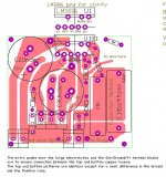
Here is an example, my first LM3886 PCB design:
TOP
BOTTOM
In my opinion you should always have the input and the output perpendicular.
This way you prevent interference.
I also recommend that you try to make the PCB much symmetric as possible.
You can also use the top layer for +Vcc and – Vcc and, the bottom layer for ground, for example.
This way you will make a small capacitor between the two layers.
( this implementation it’s very good to suppress some noise )
Try to isolate the signal with the -Vcc, +Vcc or Ground, it's also good to prevent interference.
Here is an example, my first LM3886 PCB design:
TOP
An externally hosted image should be here but it was not working when we last tested it.
BOTTOM
An externally hosted image should be here but it was not working when we last tested it.
- Home
- Amplifiers
- Chip Amps
- Improving the Non-Inverting chipamp