TL431 noise does not matter, I have a trick or two circuits, which is selected.
It is possible to achieve high parameters, just thinking alive.
CCS, Gyrator, negative resistance, and so on ... 🙂
It is possible to achieve high parameters, just thinking alive.
CCS, Gyrator, negative resistance, and so on ... 🙂
Attachments
Dac PS
Hi Guys,
I would like to know if somebody tried this circuit for analog and digital DAC PS. And if yes what's your comments on the PS? Thank you! Maxpou
http://www.diyaudio.com/forums/powe...ing-lm3x7-regulator-circuit-4.html#post356154
Hi Guys,
I would like to know if somebody tried this circuit for analog and digital DAC PS. And if yes what's your comments on the PS? Thank you! Maxpou
http://www.diyaudio.com/forums/powe...ing-lm3x7-regulator-circuit-4.html#post356154
Wow, just read this entire thread (yeah took a good hour) and I am intrigued by this. Mostly Fred's circuit with 1 bjt (post #34)
What is the typical output current that can be expected from this? is it the same as what one could get from a 317 by itself?
I'm looking to drive 5 double op amps at ±15V for an active filter setup and I want to make sure it won't be too noisy.
What is the typical output current that can be expected from this? is it the same as what one could get from a 317 by itself?
I'm looking to drive 5 double op amps at ±15V for an active filter setup and I want to make sure it won't be too noisy.
Hi ZLyzen, The output current is unaffected by the transistor. It is used to improve the noise rejection of the reg.
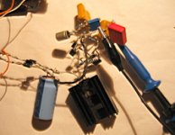
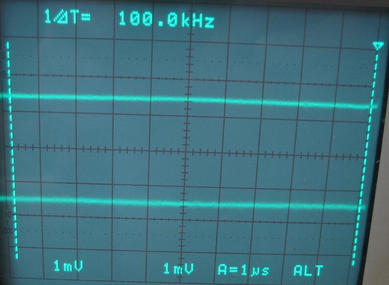
I have built a dual rail supply based on this idea from Fred, though I used two LM317's not the usual LM317 and LM337. latest test results here ---> http://www.diyaudio.com/forums/powe...7-experiments-measurements-3.html#post2834444
Earlier in the thread I posted differences between a standard setup and with the BJT. ---> http://www.diyaudio.com/forums/powe...7-experiments-measurements-3.html#post2834444 Note that at that point I had quite a few noise issues with my sound card preamp causing 50Hz interference, however the difference between the standard, and BJT circuit should be apparent 🙂 The standard circuit is improved by increasing the size of the bypass cap, but as can be seen it has little effect with the BJT circuit. This was the escence of Fred's design I think. that it was possible to use a small quality film cap for the bypass, rather than a much larger electrolytic.
Tony.
Great! would something like a 2N3904 be a good transistor (I have basically zero experience with them in circuits)
Looking at his sample diagram how do you set the voltage for the regulator?
How do Tantalum Capacitors work for the bypass? performance wise
Looking at his sample diagram how do you set the voltage for the regulator?
How do Tantalum Capacitors work for the bypass? performance wise
2n3904 appears to be an npn transistor, you need pnp for the LM317 circuit. I used BC560C's in my circuit. The higher the Hfe the better but aim for something with a hfe > 400 at least. The 2n3904 falls down on that as well. I think Fred may have made some suggestions for different transistors earlier in the thread.
I used a multiturn trimpot for the bottom resistor, I could not get a calculation to work to predict correct resistor values for setting the voltage.
The schematic for my overkill realisation of this idea attached below. You can ignore the CRC front end if all you want is a working version of the reg part of the circuit and if you only want a single rail just use the top half of the circuit🙂 The more traditional approach (for dual rail) would be to use an LM337 for the bottom reg, and I think you would then need to use an npn transistor for the negative part of the circuit.
Tony.
edit: note that the copyright notice on the schematic was me being anal, I always put them on my photos. It should not be in any way taken as a restriction on what you can do with the circuit 🙂
Attachments
Last edited:
awesome, thanks a lot Tony, checking out the circuit gunna throw it together in multisim and see if I can get 15V
If multisim is compatible with LTSpice then a ready made spice model (somewhat older revision) is available on my blog page http://www.diyaudio.com/forums/blog...egulated-power-supply-updated-2011-02-10.html
Tony.
Tony.
Last edited:
@wintermute
your post #127, output voltage formula (simplified):
Vout = ((Vadj + Vbe) * (R9 + VR1)) / VR1
If R9 = 10K, VR1 = 2K, Vbe = 0.65V, Vadj = 1.25V, then:
Vout = ((1.25V + 0.65V) * (10000 + 2000)) / 2000
Vout = (1.90V * 12000) / 2000
Vout = 11.4V
This is very simplified formula, enough for rough calculation (base current left out, base resistor left out, Vbe slope left out, temperature left out,....).
Last edited:
Thanks Stormsonic, I just measured the pots on my board, and they are set at 8.3K that is for a 10.0V output. I can't measure the Vbe at the moment because the new case is only half assembled, and the mains wiring is not yet complete.
The really odd thing is that in the spice simulation I need 41K for the lower resistor to get 10V (which is why I got the 50K pot 🙄 I suspect that my BC560c model is a bit off!!
8.3K gives me +- 3.6V
Tony.
The really odd thing is that in the spice simulation I need 41K for the lower resistor to get 10V (which is why I got the 50K pot 🙄 I suspect that my BC560c model is a bit off!!
8.3K gives me +- 3.6V
Tony.
If you want +10V output, base of Q1 must be +8.1V (roughly).
8.1V + 0.65V(Vbe) = 8.75V at Adj pin. Between LM317's ADJ and OUT pin will ALWAYS! be 1.25V, therefore 8.75V + 1.25V = 10V.
R7 is limiting your current through Q1 to 1.25mA. BC560C's Hfe is high (400 or 500), therefore base current over 100R base resistor and voltage drop over R8 is negligible. This base current will also run through VR1 to ground, but it is only few nA, can be left out.
If VR1 = 8.3K, you will have ~ 4.19V at output.
Last edited:
There's something odd going on then. The hfe of the BC560's were about 435 from memory. VR1 was measured at 8.3K and output voltage is 10.05V I'll have to double check that the top resistor is actually 10K! This is the actual circuit not the simulation 🙂
edit: My bad I should have looked at the circuit again before doing the measurement of the pot IN circuit 🙄 The pot is effectively in parallel with 10.2K (actually 10.261 K as the resistors are 523 ohm not what they are on the schematic as I couldn't get the value). So the real value of the pot is ~43.43K which is much closer to what I had in the sim. Math may be a bit off because it is now 2012 and I've had a few glasses of wine Happy New Year! 🙂
Tony.
edit: My bad I should have looked at the circuit again before doing the measurement of the pot IN circuit 🙄 The pot is effectively in parallel with 10.2K (actually 10.261 K as the resistors are 523 ohm not what they are on the schematic as I couldn't get the value). So the real value of the pot is ~43.43K which is much closer to what I had in the sim. Math may be a bit off because it is now 2012 and I've had a few glasses of wine
Happy New Year! 🙂 Tony.
Last edited:
Ups, yes, my mistake with the formula. Should not be divided with VR1, but divided with R9.
This one is correct:
Vout = ((Vadj + Vbe) * (R9 + VR1)) / R9
mea culpa 😱
Happy New Year to all 😀
This one is correct:
Vout = ((Vadj + Vbe) * (R9 + VR1)) / R9
mea culpa 😱
Happy New Year to all 😀
Last edited:
Ah thanks! that works 😀 . That was the one thing that bugged me about the circuit, not being able to work out the formula for calculating the resistance. I'll add the formula to the blog entry with a credit if that's ok 🙂
Tony.
Tony.
Wintermute,
Thanks for your posts/blogs on improving the LM317 regulator. Very informative.
I am currently researching a low noise power supply for the ESS9018 DAC I'm designing, and I wonder why you aren't looking into a newer part like the LT1763 which has a much better noise figure to start with and does not need as much auxillary circuitry to get its noise down?
Hi deanbob. Mostly this was a learning exercise for me. It is the first electronics circuit I have "designed"* myself (apart from some very simple circuits).
But when it came down to it, I wanted the circuit to be able to supply higher currents if needed (the LM317 can go all the way up to 1.5A if properly heatsinked) and apart from that, nothing else that I looked at had as good ripple rejection as the LM317.
Fred's circuit appealed to my predilection for wanting to wring the very most performance out of something (I think the comment was made early in the thread about trying to make a silk purse out of a sow's ear) , and so my journey of designing a rather unconventional power-supply based on a very conventional core (ie the LM317) started 🙂
* I say designed rather loosely as It was more a case of I looked at fred's circuit, worked out what values I needed to get it working, using LTSpice, and then decided to try using relative voltages as the means for doing the negative rail using another identical circuit. I wasn't sure whether it would actually work until I built it on the breadboard. So it more came out of reading datasheets and experimenting than any solid engineering, or electronics theory, as I am pretty light on in the latter 🙂
Tony.
if you want the best of both worlds (LM317 and LT1763), go with the lt1963A (1.5A) or lt1764A (3A) very good noise figures, very low dropout, SMD with a small area of copper pour being all thats needed for heatsinking and to top it off, the LT datasheets are superb
@Tony
it is OK for me, but i feel credit should really go to Fred & other contributors.
And LM317 can supply over 2A, if needed.
it is OK for me, but i feel credit should really go to Fred & other contributors.
And LM317 can supply over 2A, if needed.
Trouble with the LT series regulators is their ripple rejection is reasonably poor compared to the LM series although much lower noise, so you need some form of ripple filter before the regulator (like a capacitor multiplier or RC filter as per wintermute's test cct)
- Home
- Amplifiers
- Power Supplies
- Improving the LM3x7 regulator circuit