Hello,
Currently listening with LM3886 amplifier 20,000μF for each side in the psu.
The sound is very detailed, and have dark sound signature.
But the highs is not pleasant and the mids is laid back.
In summary the sound not "live" as the great LM1875.
Are there any recommendations how to improve the LM3886?
Schematic of amplifier:
An externally hosted image should be here but it was not working when we last tested it.
Last edited:
I too found the LM3886 a bit dull when compared to the true greats of the audio world. It is cheap and it is easy for those on a limited budget but it can be bettered many times over by discrete circuit designs.
I too found the LM3886 a bit dull when compared to the true greats of the audio world. It is cheap and it is easy for those on a limited budget but it can be bettered many times over by discrete circuit designs.
I second that!😉
I too found the LM3886 a bit dull when compared to the true greats of the audio world. It is cheap and it is easy for those on a limited budget but it can be bettered many times over by discrete circuit designs.
I second that!😉
Every thread in the Chip Amp forum has to have, by law, at least one post about discretes being better.
That PCB layout looks terrible, the bypass caps are too small and too far away from the chip pins. I recommend checking for HF oscillation or transient circuit instability.
Mike
Mike
Do you mean as in thread-jacking a thread that is only about a chip amp? Does that happen here? Surely not!Every thread in the Chip Amp forum has to have, by law, at least one post about discretes being better.
FOXYE, do you have a schematic and a photo of the entire amp?
Abs
Are there any recommendations how to improve the LM3886?
The most common mistake I've seen with chipamps is in the layout - poor gronding hygiene. Not keeping signal and power grounds separate IOW.
Show a schematic for how the decoupling caps are wired up, topologically?
C6, input cap, you can up grade .
C11, C12 are too small , increase to 1000 microF with C for audio.
C11, C12 are too small , increase to 1000 microF with C for audio.
Last edited:
Hello,
But the highs is not pleasant...
I've said it before and I'll say it again, this amplifier needs to have feedback compensation. Try a 27pf capacitor in parallel with R10 and see if there's an improvement.
Also, not helping things is that this layout is terrible, rip out the two small decoupling caps and place them right on the chips pins. 100nF X7R caps are perfect for this job.
I hope this helps.
How does the power supply look? Schematic please
Member
Joined 2009
Paid Member
A couple years ago Bob Cordell showed the New Jersey Audio Society how to build a chip-amp based upon the LM3886 -- we had it in comparison to a Pass Aleph (not a DIY Aleph) and hotted up Thors.
The secret is no secret -- it's in his book -- you want to drive the inverting input of the LM3886, not the non-inverting input.
The secret is no secret -- it's in his book -- you want to drive the inverting input of the LM3886, not the non-inverting input.
Silva mica or NP0 ceramic are both fine for this purpose.
I second this.
Just get a stack of different NP0 caps at varying values from 10pF to 47pf and see what works for you. Silver mica can be a touch expensive, so I only ever use it when I'm positive I have the correct value.
Feedback Resistor is R10.Isn't R12 meant to be as close to the pins as possible?
FOXYE, do you have a schematic and a photo of the entire amp?
Abs
Abs,
Dont have the schematic of amplifier. I'll try make one and upload later.
I uploaded photos to the beginning of the thread. 🙂
Schematic of amplifier:
An externally hosted image should be here but it was not working when we last tested it.
How are the Cs (from pins 1,4 & 5) routed at their 0V end? IME these are problem components as if they go direct to the 0V end of Ci or R2 there'll be grittiness in the sound.
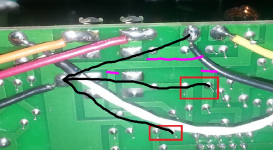
Cuts and straps to implement star grounding (of a sort)
The cuts to make in the copper I've shown in magenta. Wires to add are shown in black. You'll still have a loop (because the signal cable running left-right has its shield in parallel with a PCB track) but I'm hoping there's no nearby field....😛
The cuts to make in the copper I've shown in magenta. Wires to add are shown in black. You'll still have a loop (because the signal cable running left-right has its shield in parallel with a PCB track) but I'm hoping there's no nearby field....😛
Attachments
WARNING!!!
Remove 220 VDC connection from PCB.
Replace Ci for one in the range of 47 - 100 uF.
Move Cin to parallel with R2.
Looks like the input signal is filtered by parts of the pre amp. You need to redesign (rebuild) the input section of the amp. Missing input cap in schematics (2-4uf).
Remove 220 VDC connection from PCB.
Replace Ci for one in the range of 47 - 100 uF.
Move Cin to parallel with R2.
Looks like the input signal is filtered by parts of the pre amp. You need to redesign (rebuild) the input section of the amp. Missing input cap in schematics (2-4uf).
This is the best chipamp you can make -- the LM4780 is, of course, 2 LM3886's so just adopt for your purposes:
An externally hosted image should be here but it was not working when we last tested it.
- Status
- Not open for further replies.
- Home
- Amplifiers
- Chip Amps
- Improving the LM3886 amplifier