Well I was thinking that its not really just the CCS trim pot that needs to be adjusted. The two bias resistors at the top of the circuit need to be adjusted in tandem or you loose a lot of voltage swing... Thats one reason I was thinking about active loads instead of resistors at the top of the circuit.
Cheers!
Russ
Cheers!
Russ
Russ White said:Well I was thinking that its not really just the CCS trim pot that needs to be adjusted. The two bias resistors at the top of the circuit need to be adjusted in tandem or you loose a lot of voltage swing... Thats one reason I was thinking about active loads instead of resistors at the top of the circuit.
Cheers!
Russ
hehe.........that's your choice
you really don't need any tweaking of load resistors if you have no intention to chase output offset ;simple changing of these resistors is more than enough.........in purpose of setting desired voltage swing.
in any case-you can't make every-purpose-preamp from this simple construction ; choose one thing (say as current through halves) then adjust other parameters to that
you have one more tool than I have.......... sim..... I just have no time for that........
Re: Re: Re: Lotus.?.?.?
Steen🙂
Yep, I think you are right! I just let the BosoZ run at 19dB gain with the A-X's. I will try and lower the gain. Thanks Babowana🙂Babowana said:
I think it's due to the fuction of total gain and distortion.
The gain of pre+F4 depends on the pre amp gain alone
while the gain of pre+AX is pre gain times power amp gain.
I guess that your description of top end sound means
that the top end is too much and out of tone-balance.
I usually try to get normal listening level at about 10-11
o'clock volume knob, saving total gain at proper level ^^;

The SK389's are not all that well matched after all!(Only to within 3%) I would be just as happy using 2 SK170's, as long as they are thermally connected🙂BrianDonegan said:Does anyone have an opinion of using the dual 389 vs two 170s?
Benefits of the 389 are better thermal coupling and claimed better matching (likely). Benefit of 170's is that you can use original 2SK170B or the LSK170B.
Thoughts?
Steen🙂
Re: Re: Re: Re: Lotus.?.?.?
Hi Steen,
I am thinking along he SK170 line right now as well, but for layout reasons. 🙂
I think I will stick with single devices for all the Qs, but right next to each other so they can be thermally coupled. 🙂
I am working on a layout right now.
Cheers!
Russ
steenoe said:The SK389's are not all that well matched after all!(Only to within 3%) I would be just as happy using 2 SK170's, as long as they are thermally connected🙂
Steen🙂
Hi Steen,
I am thinking along he SK170 line right now as well, but for layout reasons. 🙂
I think I will stick with single devices for all the Qs, but right next to each other so they can be thermally coupled. 🙂
I am working on a layout right now.
Cheers!
Russ
Russ White said:
Looking at the datasheet for the LSK389 I see that the "B" version has a minimum saturation current of 6ma and a max of 12ma.
Thats quite a range.
I guess I have to plan for the worst?
I suppose I should probably aim for just over half the lowest possible sat current which would be 6ma. So 3ma bias current? or should I go up a bit say to 4ma and hope that I don't saturate?
As I recall it, the rule of thumb was to set the circuit for .5-.6 of Idss. That's the actual Idss, not a number plucked from a spec sheet. Yes, that means testing the devices.
If you assume the midpoint of the range--in this case, 9mA--then a 6mA device would be rather overdriven. Maybe okay for a guitar amp, but not so good for hifi use. If you don't want to test devices, shoot for something like 3 to 3.5mA and you'll be fine. In this case, it's better to underdo the current than overdo it.
Grey
Thank You Grey, that confirms what I was thinking. Glad to see I was not far off the mark. This is a bit new to me, so I very much appreciate the input.
Cheers!
Russ
Cheers!
Russ
I don't know how many devices you are planning on buying, but if you get some with a low end Vgs off, say -.4 volts, then you will have to attenuate your CD's input signal a whole bunch ( down to roughly .15 volts AC) to prevent distortion that occurs when gate current begins to when the device is forward biased, or when it starts to turn off because you are approaching Vgs off.
I have a test circuit on my bench with jfets that are approximately -.5v Vgs off. (cascoded). By the time I reduce the input, I can only get a maximum of roughly 2V ac before distortion sets in.
JJ
I have a test circuit on my bench with jfets that are approximately -.5v Vgs off. (cascoded). By the time I reduce the input, I can only get a maximum of roughly 2V ac before distortion sets in.
JJ
jupiterjune said:I have a test circuit on my bench with jfets that are approximately -.5v Vgs off. (cascoded). By the time I reduce the input, I can only get a maximum of roughly 2V ac before distortion sets in.
JJ
What sort of circuit is that you are testing? A straight follower?
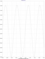
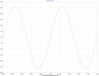
The way this circuit works with feedback you should only even see something like 350mv on the gate (6Vpp signal).
Here is a graph of the Vgs with a balanced 6Vpp signal.
Attachments
Quick EZ question here that kind of got lost in the more elaborate questions being asked....
IF the X-BOSOZ is operated in balanced mode (balanced in and balanced out). Does it have enough poop for the F4?
My understanding is that it puts out more in the balanced mode?
I realize it depends on the speaker. Mine are about 95 dB efficient so probably OK in about any case, but let's say for 90dB/1/1 efficient speakers?
Variac said:Quick EZ question here that kind of got lost in the more elaborate questions being asked....
IF the X-BOSOZ is operated in balanced mode (balanced in and balanced out). Does it have enough poop for the F4?
My understanding is that it puts out more in the balanced mode?
I realize it depends on the speaker. Mine are about 95 dB efficient so probably OK in about any case, but let's say for 90dB/1/1 efficient speakers?
Yes it does. 🙂
If you run the XBOSOZ at 60V VDD with the bias set correctly so that the amp idles with the voltage on the outputs(before caps) at 30V (1/2 VDD) if can do about +/-21V output before clipping.
THD at that output will be about .1% with 48K load.
You could drive the F4(with 22V rails) easily close to clipping.
I am trying to figure out the best gain for most equipment. We have to remember to add 6db for SE input.
:EDIT: I was off on swing, its actually 21-22V :EDIT:
Cheers!
Russ
Of course (at least on this circuit) if you really need more output swing you could raise the VDD rail voltage if you choose suitable transistors for Q1/Q2 (cascdode NPN BJTs) . You would also have to calculate new bias resistors etc.
Cheers!
Russ
Cheers!
Russ
just to add more to my musings about bias point ..........
when I mention that is nice to implement trimpot in ccs, I meant that in this way is easy to correct settings to any used jfet.........regarding Idss
I know that some big boys use 3 to 4 mA range (Iq) for 2SK389BL and 2SJ109BL family . that's per half.
some other boy (little smaller) use 5mA per half for 2SJ109BL .....
say that you wanna use J310 ........as Babowana ......that's his nice little jfet ......you can use twice or trice more.......and you can find that specimens easily in sum of 100 pieces........
so-Grey is certainly right saying
what you'll use in fact depends solely of estimated input voltage swing for sayed jfet
point of this post is
everything else is usual ZM mumbo jumbo

when I mention that is nice to implement trimpot in ccs, I meant that in this way is easy to correct settings to any used jfet.........regarding Idss
I know that some big boys use 3 to 4 mA range (Iq) for 2SK389BL and 2SJ109BL family . that's per half.
some other boy (little smaller) use 5mA per half for 2SJ109BL .....
say that you wanna use J310 ........as Babowana ......that's his nice little jfet ......you can use twice or trice more.......and you can find that specimens easily in sum of 100 pieces........
so-Grey is certainly right saying
As I recall it, the rule of thumb was to set the circuit for .5-.6 of Idss.
what you'll use in fact depends solely of estimated input voltage swing for sayed jfet
point of this post is
I know that some big boys use 3 to 4 mA range (Iq) for 2SK389BL and 2SJ109BL family . that's per half.
everything else is usual ZM mumbo jumbo
Zen Mod said:
I know that some big boys use 3 to 4 mA range (Iq) for 2SK389BL and 2SJ109BL family . that's per half.
Excellent, that is what I am shooting for, the PCB will be flexible enough for any of those bias settings.
Cheers!
Russ
Russ-
QUOTE]What sort of circuit is that you are testing? A straight follower?[/QUOTE] Sorry, I guess you're not a psychic.🙁
I should have said it is a cascoded bal-zen-pre. A 2N4416A jfet is cascoded with an IRF610.
The major differences are:
1) R2 and R3 on my bench = 750 ohms each, so I would expect much lower gain (but that is not the concern here)
2) CCS is a resistor of 1500 ohms off a 25 volt rail.
3) no 4.7 ohm resistors at sources of j-fets.
4) my cascode voltage is derived by a voltage divider off of the positive voltage rail to ground.
I don't see anything here (intuitively) that would account for the difference.
Wouldn't your source voltage be DC--especially if you are driving this balanced?
Is 4.7 ohms the correct value on your schematic?--this doesn't seem like enough resistance to account for the voltage there following the input up 6V pp.
JJ
Wouldn't your source voltage be DC--especially if you are driving this balanced?
Are you referring to the input signal? It should have no DC component (ideally).
Hi Jupiter,
The way the input works the gate of the JFET only sees a small fraction of the input voltage, the feedback current drives the gate back (via RF) toward GND. Something would have to be very wrong for the gate to see more the a few hundred millivolts.
It works just like a fully symmetrical opamp like the THS4131, where the inputs are driven toward Vocm by the outputs. Thats why the input impedance is determined by RG1 and RG2.
There will be a current flowing through RF1 to negate the current through RG1 (with the same effect through Rf2 and RG2). That will drive the voltage at the gate toward zero, classic negative feedback.
The only way that you would get a high enough voltage at the gate to be worrisome would be if you ran out of gain or something. That could only happen if the preamp was not able to generate enough current through RF to counteract the current through RG, that sounds like clipping to me.
It is no different in this respect for the standard XBOSOZ. The fact that its a JFET instead of the MOSFET makes no difference really.
Anyway that is how I understand it and thats how it simulates. It is also how my regular XBOSOZ works (tested on bench). I don't see how this would be any different.
Cheers!
Russ
jupiterjune said:
4) my cascode voltage is derived by a voltage divider off of the positive voltage rail to ground.
JJ
That might be a problem. The cascode voltage should not be referenced from GND but from source of the JFETs(the top of the CCS). They will not exactly be at GND.
Natural extension....
Ok I was just thinking... (always dangerous)
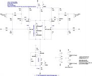
One could beef up the current delivering capacity and make a power amp or at least a headphone amp. 🙂
Here is an example of something that might work, I have no idea as I have not tested it, but it simulates fine. The FETs would need appropriate heatsinks.
Forgive the resistor current sinks they could be active.
I simulated for 32ohm cans.
Cheers!
Russ
Ok I was just thinking... (always dangerous)
One could beef up the current delivering capacity and make a power amp or at least a headphone amp. 🙂
Here is an example of something that might work, I have no idea as I have not tested it, but it simulates fine. The FETs would need appropriate heatsinks.
Forgive the resistor current sinks they could be active.
I simulated for 32ohm cans.
Cheers!
Russ
Attachments
The way the input works the gate of the JFET only sees a small fraction of the input voltage, the feedback current drives the gate back (via RF) toward GND. Something would have to be very wrong for the gate to see more the a few hundred millivolts
Thanks--I am sure that is it. Very interesting to note how different this works from the original BOSOZ, which didn't have X feedback, and therefore worked a bit differently....
I just have a pot in the voltage divider--I just adjust it till things work. I will be trying the zeners -- it seems to be a much better way to go.
JJ
- Status
- Not open for further replies.
- Home
- Amplifiers
- Pass Labs
- Improving on X-BosoZ to mate the F4