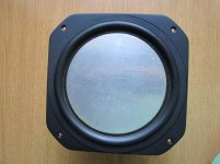
Improvement the speaker with flat sandwich diaphragm.
Noticed that a large part of the flat inner diaphragm is large. More than the edges. What triggers a significant resonans.
It is easy to detect finger impacts. This will sound.
Extended voice coil element, which increases rigidity. Using a thick paper, Kevlar and carbon fiber.
Adding a slight weight.
Attachments

Last edited:
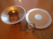
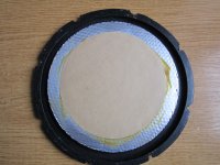
Even better is obtained when instead of a paper rings using a paper circle.
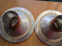
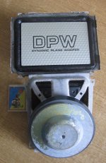
Photography upgrade next pair of 50GDN-1.
Old glue trimmed to the level of the foil. Completely remove is required.
In the second photo donor for a couple, of future cells speakers diameter of 5 "-5.5"
Photography upgrade next pair of 50GDN-1.
Old glue trimmed to the level of the foil. Completely remove is required.
In the second photo donor for a couple, of future cells speakers diameter of 5 "-5.5"
Attachments
Last edited:
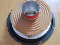
Initially, speakers be of not the workers.
Regained, with the upgrade.
Features one of them 8,5", after recovery :
......... Re, Ohm; ..... Fs, Hz; .... Qa; .... Qe; ...... Qt ...... Vas, l
№1 .... 6,7 .......... 31,8 ...... 2,88 ... 0,385 ... 0,34 .. ... 48
Most importantly, the sound improved. In the midrange.
Regained, with the upgrade.
Features one of them 8,5", after recovery :
......... Re, Ohm; ..... Fs, Hz; .... Qa; .... Qe; ...... Qt ...... Vas, l
№1 .... 6,7 .......... 31,8 ...... 2,88 ... 0,385 ... 0,34 .. ... 48
Most importantly, the sound improved. In the midrange.
As I just posted somewhere else, flat honeycomb diaphragms I was experimenting with had very good dispersion.
Svjatoslav:
That is a very cool construction! (And one I've had in my mind to attempt for a long time.) To my knowledge, this type of cone assembly is either built on a jig (fixture) or built up in the speaker basket & magnet assembly in order to align the parts. In either method, the voice coil is shimmed around the magnet centre pole for proper gap while the spider and surround are glued to the frame. The shims are then withdrawn, and the dust cap is glued on. Since you have no accessible opening to fit & remove the shims, how do you achieve the required clearance in that very precise gap for the voice coil?😕 I wonder if you would kindly share your secret?
Thanks,
Wilf
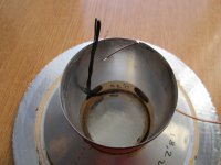
There is no secret. Centering on external backlash.
Set to the whole mobile system. In assembly.
In a magnetic gap is set 8 cuts of copper wire. Symmetrically. A little less backlash. Wires are vented outside the frame outward. And there are fixed so as not were shifted.
Lower suspension ("spider ") is pasted on them. After partial drying glue, wire must be pulled out smoothly.
Last edited:
Ahhh - very clever! Once again proving "there's more than one way to ..." Thanks for sharing this tip! 🙂
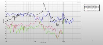
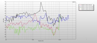
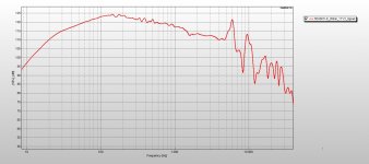
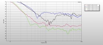
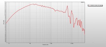
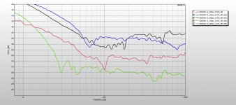
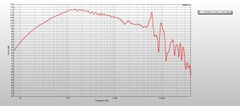
The measured characteristics of the speaker (post 1).
It seems that the mode of the piston up to 5 kHz. At 2 kHz resonance, allegedly, suspension.
Measurements at different distances from the center of the disc. At different levels of applied voltage.
It seems that the mode of the piston up to 5 kHz. At 2 kHz resonance, allegedly, suspension.
Measurements at different distances from the center of the disc. At different levels of applied voltage.
Attachments
-
 50GDN1-8_315mm_5V6_HD.jpg252.9 KB · Views: 184
 -
 50GDN1-8_315mm_2V83_HD.jpg250.4 KB · Views: 189
 -
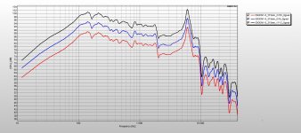 50GDN1-8_315mm_2V83_5V6_11V2_0grad.jpg271.5 KB · Views: 194
 -
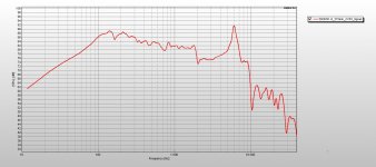 50GDN1-8_315mm_2V83_0grad.jpg224.1 KB · Views: 182
 -
 50GDN1-8_20mm_11V2_HD.jpg212.3 KB · Views: 193
 -
 50GDN1-8_20mm_11V2_0grad.jpg207.3 KB · Views: 196
 -
 50GDN1-8_20mm_5V6_HD.jpg219.8 KB · Views: 192
 -
 50GDN1-8_20mm_5V6_0grad.jpg237.1 KB · Views: 198
 -
 50GDN1-8_20mm_2V83_HD.jpg224.2 KB · Views: 223
 -
 50GDN1-8_20mm_2V83_0grad.jpg236.3 KB · Views: 315
The equipment and methods of measurement are similar to those reported 47 this topic:
http://www.diyaudio.com/forums/full-range/218603-speakers-full-range-high-resistance-5.html
http://www.diyaudio.com/forums/full-range/218603-speakers-full-range-high-resistance-5.html
Attachments
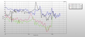
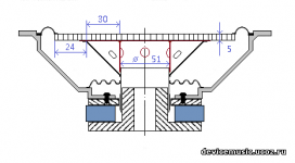
Figure improvement 50GDN-1, with the dimensions (millimeters). Brown - paper insert.
Attachments
Last edited:
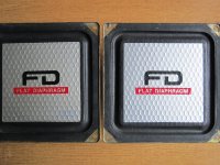
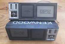
Into the theme collection. Recovered KENWOOD loudspeakers with rectangular cell membrane. Constructively made with two centering washers. One of which is ... inside a magnetic system!)))
Attachments
Last edited:
have some cheap speakers that I really like,
will glad to hear how to improve them or make some better crossover
Sony APM D5
*the 1" top tweeter I took from another speakers


also I have some mic for measurements (Umik1)
can someone send me please for some guide, how to make some good measurments?
(I done some before with headphones)
thanks.
will glad to hear how to improve them or make some better crossover
Sony APM D5
*the 1" top tweeter I took from another speakers
also I have some mic for measurements (Umik1)
can someone send me please for some guide, how to make some good measurments?
(I done some before with headphones)
thanks.
And what's the crossover there now?
It is necessary to know the dependence of the loudspeaker resistance on the frequency and their characteristics
It is necessary to know the dependence of the loudspeaker resistance on the frequency and their characteristics
And what's the crossover there now?
It is necessary to know the dependence of the loudspeaker resistance on the frequency and their characteristics
The wrote impedance is:
woofer (6") 6ohm
tweeter (2") 7ohm
I add tweeter (1") 8ohm
Original crossover
Woofer 6" - no crossover
tweeter 2" - 0.39mH coil parallel and 2.2uf capacitor serial
piezo - parallel connected to the tweeter
*I guess something like 4000kHz-5000kHz crossover and 75db speaker
have large variety of elements (coils and capacitors).
planned to work with them but stop unfortunately the progress 🙁
Last edited:
Also a fairly good crossover.
Apparently, the choke on the core of ferrite, and the capacitor електроIitic? If so, it would be a good idea to replace it with a membranous (PET, PS).
Apparently, the choke on the core of ferrite, and the capacitor електроIitic? If so, it would be a good idea to replace it with a membranous (PET, PS).
Yes I know
made some stupid decisions in the past
the parallel tweeter coil has an air core
the other caps is WIMA MKP10 (or 4) {Poly.... capacitors}
stupidly calculate all with the resistance and not with the incidence of the elements
Also wanted to make some crossover for the woofer.
made this schematic without any basic knowledge or measurements

*I really hope that I remembered to reverse the tweeter polarity.
https://i.imgur.com/xGV952K.png
and solder all without any PCB with wires


First plan and look
https://s17.postimg.io/am6oy8pin/IMG_20160904_051955.jpg
https://s17.postimg.io/fz04q42sv/IMG_20160904_052116.jpg
adding some handle on the top
https://s17.postimg.io/plgpwkyu7/IMG_20160917_200347.jpg
I done all this with low skills and just leave it.
and yes, this speaker is my first attempt to mod speakers.
not an easy job.
plan to rebuild all this structure and the crossover too.
made some stupid decisions in the past
the parallel tweeter coil has an air core
the other caps is WIMA MKP10 (or 4) {Poly.... capacitors}
stupidly calculate all with the resistance and not with the incidence of the elements
Also wanted to make some crossover for the woofer.
made this schematic without any basic knowledge or measurements
*I really hope that I remembered to reverse the tweeter polarity.
https://i.imgur.com/xGV952K.png
and solder all without any PCB with wires
First plan and look
https://s17.postimg.io/am6oy8pin/IMG_20160904_051955.jpg
https://s17.postimg.io/fz04q42sv/IMG_20160904_052116.jpg
adding some handle on the top
https://s17.postimg.io/plgpwkyu7/IMG_20160917_200347.jpg
I done all this with low skills and just leave it.
and yes, this speaker is my first attempt to mod speakers.
not an easy job.
plan to rebuild all this structure and the crossover too.
Last edited:
Thus, with one crossover order, the polarity of the links must be reversed.
A crossover is required on a low-frequency speaker. To exclude the membrane resonance zone.
Piezo - parallel connected to the tweeter.
Two coils, two capacitors, alignment resistor.
You need to find (measure) the resistance of both speakers near the dividing zone.
A crossover is required on a low-frequency speaker. To exclude the membrane resonance zone.
Piezo - parallel connected to the tweeter.
Two coils, two capacitors, alignment resistor.
You need to find (measure) the resistance of both speakers near the dividing zone.
Last edited:
Thus, with one crossover order, the polarity of the links must be reversed.
A crossover is required on a low-frequency speaker. To exclude the membrane resonance zone.
Piezo - parallel connected to the tweeter.
Two coils, two capacitors, alignment resistor.
You need to find (measure) the resistance of both speakers near the dividing zone.
Can you send me here some guide how to measure the elements?
What the distance to put the microphone from the speaker?
Can you send some crossover guide ?
Thanks.
- Home
- Loudspeakers
- Planars & Exotics
- Improvement the speaker with flat sandwich cone