Double Differential Input Push-Pull EF-VAS Bias Revisited - again
So, I finally took the old RA-971 down off the shelf and pulled the VAS modules. Yes, all the VAS transistors were dead.
Then back to the ”fumble-board” to re-populate it again. After the usual breadboard flying wire mistakes, I seemingly got the circuit working – now under even tighter current supply limiting.
The first thing I noticed as different was that one VAS transistor was cold, but the other very hot. So, with these two (non-matched) TO-92 transistors the current sharing apparently did not work. I didn’t want to do any matching, as the module would have SOT-23 versions – that are not easily selected/matched.
I wanted to increase the emitter resistors anyway to give the new CM2 current mirror some more voltage headroom, so I increased the 33R to 100R’s - and that helped the current sharing.
Then I put in a 100R trimmer in the mirror emitter on the fumble-board to adjust the required 6 mA total VAS output current.
You would think that transforming a 9mA mirror control current down to 3 mA through each of the the VAS’s 100R’s - a 33R emitter resistor would be needed. But apparently - no.
Instead the trimmer needed to be set to about 19R, over 5 times lower than the 100R’s - say what ???
I am not sure why that is so, but I suppose that the operating point parameters change quite a bit between having 9 mA and 3 mA through a small signal transistor like the C1845. Anyway, I never argue with reality, so - 19R6 it was.

You only need one of the modules to be equipped with a NCR401 current mirror control - which will nicely determine the overall bias current.
And IMHO it is better to have one than two masters fighting it out.
All these changes were put in the two VAS modules, and after a very deep breath - mounted in the 971. I also put in a 10R resistor to the bias collector for easy measurement of bias current and stability.
Result…...success! 😍
Eeeh...except - not quite.🙁
TBC
So, I finally took the old RA-971 down off the shelf and pulled the VAS modules. Yes, all the VAS transistors were dead.
Then back to the ”fumble-board” to re-populate it again. After the usual breadboard flying wire mistakes, I seemingly got the circuit working – now under even tighter current supply limiting.
The first thing I noticed as different was that one VAS transistor was cold, but the other very hot. So, with these two (non-matched) TO-92 transistors the current sharing apparently did not work. I didn’t want to do any matching, as the module would have SOT-23 versions – that are not easily selected/matched.
I wanted to increase the emitter resistors anyway to give the new CM2 current mirror some more voltage headroom, so I increased the 33R to 100R’s - and that helped the current sharing.
Then I put in a 100R trimmer in the mirror emitter on the fumble-board to adjust the required 6 mA total VAS output current.
You would think that transforming a 9mA mirror control current down to 3 mA through each of the the VAS’s 100R’s - a 33R emitter resistor would be needed. But apparently - no.
Instead the trimmer needed to be set to about 19R, over 5 times lower than the 100R’s - say what ???
I am not sure why that is so, but I suppose that the operating point parameters change quite a bit between having 9 mA and 3 mA through a small signal transistor like the C1845. Anyway, I never argue with reality, so - 19R6 it was.
You only need one of the modules to be equipped with a NCR401 current mirror control - which will nicely determine the overall bias current.
And IMHO it is better to have one than two masters fighting it out.
All these changes were put in the two VAS modules, and after a very deep breath - mounted in the 971. I also put in a 10R resistor to the bias collector for easy measurement of bias current and stability.
Result…...success! 😍
Eeeh...except - not quite.🙁
TBC

Double Differential Input Push-Pull EF-VAS Bias Revisited - again
The bias current was 6.2 mA and stable, but the VAS modules ran hot – over 60 degC, so I thought that they could probably do well with some heat sinking.
On the 971 pcb, space is at a premium, so I settled on a pair of porous ceramic types which I could cut to the right size. They also came with a self adhesive thermal tape - which worked, but I normally prefer a sturdier mechanic fixation.
A pair of the wife’s bobbypins (hair pins), cut and insulated and pressed down over the modules and heatsinks did the trick.
Temperature dropped to 50 C.


With everything now stable, all currents and temperatures under control, the amp linear from 2Hz to 120kHz, THD down to 0.003% – it was finally time to sit back and enjoy it playing on my main Angelhorns speakers, crack open a cold one while thinking back about what was achieved.🍺☺️
Firstly, the original RA-971 shows clear evidence of last minute technical design ”oops” and marketing demands. Anyone having worked in product design may/will recognize this.
The driver heat sinks that were intended to be placed on the pcb were abandoned - most probably due to driver overheating and the ”fix” was to simply clamping the drivers directly on top of one of the power transistors on the heatsink (thereby making sure that this poor transistor ran hotter than its parallel mates). And then connecting it all to the pcb by unsightly twisted heavy 30A wires.
Then, probably someone in marketing very late in the development demanded that the amp just had to have a ”preamp-out” feature (”Otherwise the amp simply won’t sell – all our competitors now have this!”)….. Does that sound familiar to some (ex-)R&D engineers?
It was (maybe too) quickly solved by knocking a RCA connector pair on a new rear plate and connecting it by brutally soldering wires to resistor leads on top of the pcb. The bare wires had to be flying high and wide to minimise hum interference from the rectifier circuit.
So, IMHO all this makes the original RA-971 look butt ugly and unprofessional inside. And these things are visible through the top air vents.
But…. that was apparently ok with marketing.

(Left channel upgraded, right channel original.)
I decided to solve the issue by slightly reducing the driver dc standing current and re-inserting the intended heatsinks immediately making things looks better. Then, replacing the ’preamp-out’ airwires with proper shielded leads below the pcb also helped the professional appearance.
I couldn’t reuse the original driver transistors, so I tried the new(ish) Toshiba TTC004/TTA004. I must say, Toshiba seems to have picked some of the best of each of their existing silicon processes into these devices and started a refreshing new part designation. High voltage, decent current capability and hFE, modest capacitance and price in a pair of new nicely linear, isolated TO-126N package devices – what’s not to like?
I wonder whether Toshiba wanted to clear out in the absolute jungle of 2SC####/2SA#### types production? Anyway, I found the 004s to be a pleasure to work with (and listen to).
And so was the upgraded amp.
But eventually, a more critical set of thoughts also started to pass my mind…..
TBC
The bias current was 6.2 mA and stable, but the VAS modules ran hot – over 60 degC, so I thought that they could probably do well with some heat sinking.
On the 971 pcb, space is at a premium, so I settled on a pair of porous ceramic types which I could cut to the right size. They also came with a self adhesive thermal tape - which worked, but I normally prefer a sturdier mechanic fixation.
A pair of the wife’s bobbypins (hair pins), cut and insulated and pressed down over the modules and heatsinks did the trick.
Temperature dropped to 50 C.
With everything now stable, all currents and temperatures under control, the amp linear from 2Hz to 120kHz, THD down to 0.003% – it was finally time to sit back and enjoy it playing on my main Angelhorns speakers, crack open a cold one while thinking back about what was achieved.🍺☺️
Firstly, the original RA-971 shows clear evidence of last minute technical design ”oops” and marketing demands. Anyone having worked in product design may/will recognize this.
The driver heat sinks that were intended to be placed on the pcb were abandoned - most probably due to driver overheating and the ”fix” was to simply clamping the drivers directly on top of one of the power transistors on the heatsink (thereby making sure that this poor transistor ran hotter than its parallel mates). And then connecting it all to the pcb by unsightly twisted heavy 30A wires.
Then, probably someone in marketing very late in the development demanded that the amp just had to have a ”preamp-out” feature (”Otherwise the amp simply won’t sell – all our competitors now have this!”)….. Does that sound familiar to some (ex-)R&D engineers?
It was (maybe too) quickly solved by knocking a RCA connector pair on a new rear plate and connecting it by brutally soldering wires to resistor leads on top of the pcb. The bare wires had to be flying high and wide to minimise hum interference from the rectifier circuit.
So, IMHO all this makes the original RA-971 look butt ugly and unprofessional inside. And these things are visible through the top air vents.
But…. that was apparently ok with marketing.
(Left channel upgraded, right channel original.)
I decided to solve the issue by slightly reducing the driver dc standing current and re-inserting the intended heatsinks immediately making things looks better. Then, replacing the ’preamp-out’ airwires with proper shielded leads below the pcb also helped the professional appearance.
I couldn’t reuse the original driver transistors, so I tried the new(ish) Toshiba TTC004/TTA004. I must say, Toshiba seems to have picked some of the best of each of their existing silicon processes into these devices and started a refreshing new part designation. High voltage, decent current capability and hFE, modest capacitance and price in a pair of new nicely linear, isolated TO-126N package devices – what’s not to like?
I wonder whether Toshiba wanted to clear out in the absolute jungle of 2SC####/2SA#### types production? Anyway, I found the 004s to be a pleasure to work with (and listen to).
And so was the upgraded amp.
But eventually, a more critical set of thoughts also started to pass my mind…..
TBC
Double Differential Input Push-Pull EF-VAS Bias Revisited – again
Well what has been achieved? A ”helicopter view” of the project brings the basic question:
Did this two year fight against a stubborn circuit challenge actually make me go OTT (over the top)?
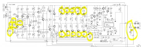
Here is a schematic (only of the the lower NPN section) of the amp showing the changes in red.

(Come to think about it – the LTP transistors were also changed by the ”TLA (Too Long Acronym)" LTP packs and should thus also have been drawn in red). So, practically everything from the input to the power stage is new…..ie. most of the amp?
I replaced one VAS transistor and two resistors with 11 transistors, 10 resistors and a couple of capacitors (And double those numbers for the entire circuit).
Referring to Gino’s earlier question whether ”simple is better?” – this is not exactly simplifying things.
Ok, the drop-in integrated modules definitely help to keep the actual component mounting work down and makes it much easier, but it still requires more complicated modules with heatsinks, ground airwires and the 10R to check the bias current, etc.
And VAS temperature control will only get increasingly more difficult when going to higher rail voltages than the RA-971’s +/-50V.
All this for what? Well ok, firstly a definite upgrade from the old Rotel sound, but perhaps a slightly more modest further improvement from the previous upgrade (which was to simply keep the original LTP collector resistors and just drilling in discrete EF transistors and their emitter resistors before the VAS).
I guess that we should always strive for ’perfection’ – but at what point does the cost of ’perfection’ become too high? (I know, I know….for some HiFi affectionados apparently never).🤑
But personally:
My engineering background says ”ok job well done, mate” for finally solving the challenge, ”but did you find the best solution – and did you actually optimize the performance gain/cost ratio? Or did you over-engineer things to get to a solution because your professional pride was challenged?”
(And why did it take you so long?)
Whereas my marketing background (yes, I was a marketing manager in my former life) says ”oh wow, that is just so brilliant (I think), now we just need some advertising buzzwords like ’Featuring improved double Wilson mirrors’ and ’Advanced current mirror voltage amplification stage’ – and this thing will sell like hotcakes (and allow me to thumb my nose at the competition)”.
(But BTW, why did it take you so long?)
In conclusion, while I believe that the fundamental concern of not ”Gilding the Lily” is valid, I still think that the result on this RA-971 justifies the effort.
It is an absolute pleasure to listen to.
And at least for me it has been a great (re-)learning process.
I plan to finish this DDiPPVAS monologue with some engineering idea ”Bloopers” (you’ve got to have those) and then perhaps some unfinished circuit ideas for anyone to comment on - or maybe try out in Spice or real life?
So yes - TBC a bit longer.
Well what has been achieved? A ”helicopter view” of the project brings the basic question:
Did this two year fight against a stubborn circuit challenge actually make me go OTT (over the top)?
Here is a schematic (only of the the lower NPN section) of the amp showing the changes in red.
(Come to think about it – the LTP transistors were also changed by the ”TLA (Too Long Acronym)" LTP packs and should thus also have been drawn in red). So, practically everything from the input to the power stage is new…..ie. most of the amp?
I replaced one VAS transistor and two resistors with 11 transistors, 10 resistors and a couple of capacitors (And double those numbers for the entire circuit).
Referring to Gino’s earlier question whether ”simple is better?” – this is not exactly simplifying things.
Ok, the drop-in integrated modules definitely help to keep the actual component mounting work down and makes it much easier, but it still requires more complicated modules with heatsinks, ground airwires and the 10R to check the bias current, etc.
And VAS temperature control will only get increasingly more difficult when going to higher rail voltages than the RA-971’s +/-50V.
All this for what? Well ok, firstly a definite upgrade from the old Rotel sound, but perhaps a slightly more modest further improvement from the previous upgrade (which was to simply keep the original LTP collector resistors and just drilling in discrete EF transistors and their emitter resistors before the VAS).
I guess that we should always strive for ’perfection’ – but at what point does the cost of ’perfection’ become too high? (I know, I know….for some HiFi affectionados apparently never).🤑
But personally:
My engineering background says ”ok job well done, mate” for finally solving the challenge, ”but did you find the best solution – and did you actually optimize the performance gain/cost ratio? Or did you over-engineer things to get to a solution because your professional pride was challenged?”
(And why did it take you so long?)
Whereas my marketing background (yes, I was a marketing manager in my former life) says ”oh wow, that is just so brilliant (I think), now we just need some advertising buzzwords like ’Featuring improved double Wilson mirrors’ and ’Advanced current mirror voltage amplification stage’ – and this thing will sell like hotcakes (and allow me to thumb my nose at the competition)”.
(But BTW, why did it take you so long?)
In conclusion, while I believe that the fundamental concern of not ”Gilding the Lily” is valid, I still think that the result on this RA-971 justifies the effort.
It is an absolute pleasure to listen to.
And at least for me it has been a great (re-)learning process.
I plan to finish this DDiPPVAS monologue with some engineering idea ”Bloopers” (you’ve got to have those) and then perhaps some unfinished circuit ideas for anyone to comment on - or maybe try out in Spice or real life?
So yes - TBC a bit longer.
Hi there Per,
So you made it to the finishline with your goal set a while ago, congratulations are in order then
In the end you explained exactly that were it all comes down to, a great learning process and hopefully a big smile or grin on your face when you are listening to some music through your Angelhorns powered by that remastered RA-971.
Although you left a small hint so I know that this is not ment for the both of my RB-991's because of the +/- 73Vdc voltagerail, a pity but every upgrade you made in the past for them worked and they both sound fantastic without breaking a sweat anymore.
cheers mate 🍻
Double Differential Input Push-Pull... etc. - On Emitter Degrading Resistors
Before I wind up, there was a question of whether what I call ”emitter degrading resistors” should really be called ”emitter degeneration resistors”.
Ehh...I don’t know, but if I had to choose I would rather be degraded than degenerated.😉 - Let's just call them 'de-g's.
Anyway, my earlier explanation of the virtues of LTP emitter degrading resistors was definitely not exhaustive: Why is it called ”degrading resistors”?
The performance of a LTP is covered elsewhere, and in detail in the heavy textbook ”Analysis and Design of Integrated Circuits” by Gray and Meyer.
I will try to give a hopefully more ”easy digestable” summary:
The LTP is a ”voltage to current” converter so the ’amplification factor’ (Iout / Vin) is called transconductance or gm [mA /V].
The mathematical relation between the output current Iout and the input voltage Vin is:
Iout = Ie x tanh (-Vin / 2Vt)
where Ie is the tail current and Vt is the thermal voltage (~26mV)
Even if you may have completely forgotten the math that you perhaps never understood - or just what tanh (tangent hyperbolicus) means, maybe intuitively it can be seen that the relationship is not linear. So the LTP gm is not linear.
It is actually a bell shaped curve centered around the 0 mV input. The gm is the highest at this point, dropping off to the sides as the input voltage either in- or decreases.

Putting in LTP emitter resistors degrades the gm drastically, but in the process also flattens the curve, thereby making the LTP amplification more linear.
(I drew it a bit off-center, sorry).
Self measured that putting in emitter degrading/generating resistors reduced distortion by a factor 10 (0.32% to 0.032%), which is truly remarkable, although it comes from a rather high starting point.
Anyway, these ’de-g’ resistors are definitely worthwhile, but they have to be very close in tolerance (as do the rest of components in the input stage).
I have chosen to use modest 68R ’de-g’ resistors, but you can see that Cordell goes much further to 470R (R3/R4 in post #825). He is apparently much less concerned with Johnson noise or low LTP transconductance.
Well, I hope all this made some sense....🤔
TBC
Before I wind up, there was a question of whether what I call ”emitter degrading resistors” should really be called ”emitter degeneration resistors”.
Ehh...I don’t know, but if I had to choose I would rather be degraded than degenerated.😉 - Let's just call them 'de-g's.
Anyway, my earlier explanation of the virtues of LTP emitter degrading resistors was definitely not exhaustive: Why is it called ”degrading resistors”?
The performance of a LTP is covered elsewhere, and in detail in the heavy textbook ”Analysis and Design of Integrated Circuits” by Gray and Meyer.
I will try to give a hopefully more ”easy digestable” summary:
The LTP is a ”voltage to current” converter so the ’amplification factor’ (Iout / Vin) is called transconductance or gm [mA /V].
The mathematical relation between the output current Iout and the input voltage Vin is:
Iout = Ie x tanh (-Vin / 2Vt)
where Ie is the tail current and Vt is the thermal voltage (~26mV)
Even if you may have completely forgotten the math that you perhaps never understood - or just what tanh (tangent hyperbolicus) means, maybe intuitively it can be seen that the relationship is not linear. So the LTP gm is not linear.
It is actually a bell shaped curve centered around the 0 mV input. The gm is the highest at this point, dropping off to the sides as the input voltage either in- or decreases.
Putting in LTP emitter resistors degrades the gm drastically, but in the process also flattens the curve, thereby making the LTP amplification more linear.
(I drew it a bit off-center, sorry).
Self measured that putting in emitter degrading/generating resistors reduced distortion by a factor 10 (0.32% to 0.032%), which is truly remarkable, although it comes from a rather high starting point.
Anyway, these ’de-g’ resistors are definitely worthwhile, but they have to be very close in tolerance (as do the rest of components in the input stage).
I have chosen to use modest 68R ’de-g’ resistors, but you can see that Cordell goes much further to 470R (R3/R4 in post #825). He is apparently much less concerned with Johnson noise or low LTP transconductance.
Well, I hope all this made some sense....🤔
TBC
Double Differential Input Push-Pull EF-VAS Bias - Bloopers
"Understanding things and getting new ideas are great virtues - but always expect reality to come around to bite your derrière". (Unknown)
So please let me show a few idea bloopers that illustrate precisely how "Good intentions are paved with roads to hell" (Me)
And probably completely embarrass myself in the process.
Firstly, I found the NCR401 to be a bit of a problem due to the high and fixed 9 mA. So an idea to fit a proper 3 mA current source with minimal parts count on the VAS module was to use a single SOT-23 JFET and a 0603 resistor in the traditional simple current source configuration.

It works….but I was very soon reminded that I had completely forgotten the significant inter-device variations in JFET's VGS and IDSS.
Even from the same tape strip of transistors, I got anywhere from under 2 to over 5 mA using the same current setting resistor value. You would have to either VGS select these ’grain sized’ SOT-23’s – or make the resistor variable - which of course would negate the entire basic idea of fitting in on the module.
Plus, these JFET current sources are not exactly temperature invariant…
So once again – Good try, but no cigar. 🚭
Then, I had the idea of moving the current source totally out of the module (completely saving it 120mW of heat👍) and up to the drop resistor
- eh, somehow.
But this meant I now had to use two separate flying wire connections, one for the EF to ground and one for the current source connection - and I didn’t think that would be tidy or look pretty.
So remembering that the EF’s collector really doesn’t need to be all the way up at ground voltage potential and also that the current through the EF transistor is a modest 0.4 mA - I thought hey ho, I’ll just connect its collector to the incoming (now 3.4 mA) current source wire connection.

I had just finished drafting this 'brilliant' solution, when the palm firmly met my forehead – Duh!
I will leave it up to the readers to see why this is an absolutely brain dead idea.
My sincere apologies to all cigar producers.
There are of course more ”bloopers” like these, but for now, I think I'd better try to forget my other ignominious embarrassments.
And perhaps just give up collecting cigars 😉
TBC
"Understanding things and getting new ideas are great virtues - but always expect reality to come around to bite your derrière". (Unknown)
So please let me show a few idea bloopers that illustrate precisely how "Good intentions are paved with roads to hell" (Me)
And probably completely embarrass myself in the process.
Firstly, I found the NCR401 to be a bit of a problem due to the high and fixed 9 mA. So an idea to fit a proper 3 mA current source with minimal parts count on the VAS module was to use a single SOT-23 JFET and a 0603 resistor in the traditional simple current source configuration.
It works….but I was very soon reminded that I had completely forgotten the significant inter-device variations in JFET's VGS and IDSS.
Even from the same tape strip of transistors, I got anywhere from under 2 to over 5 mA using the same current setting resistor value. You would have to either VGS select these ’grain sized’ SOT-23’s – or make the resistor variable - which of course would negate the entire basic idea of fitting in on the module.
Plus, these JFET current sources are not exactly temperature invariant…
So once again – Good try, but no cigar. 🚭
Then, I had the idea of moving the current source totally out of the module (completely saving it 120mW of heat👍) and up to the drop resistor
- eh, somehow.
But this meant I now had to use two separate flying wire connections, one for the EF to ground and one for the current source connection - and I didn’t think that would be tidy or look pretty.
So remembering that the EF’s collector really doesn’t need to be all the way up at ground voltage potential and also that the current through the EF transistor is a modest 0.4 mA - I thought hey ho, I’ll just connect its collector to the incoming (now 3.4 mA) current source wire connection.
I had just finished drafting this 'brilliant' solution, when the palm firmly met my forehead – Duh!
I will leave it up to the readers to see why this is an absolutely brain dead idea.
My sincere apologies to all cigar producers.
There are of course more ”bloopers” like these, but for now, I think I'd better try to forget my other ignominious embarrassments.
And perhaps just give up collecting cigars 😉
TBC
Last edited:
Hi! I've been curiously following this fantastic thread for such a long time now, ended up selling my two expensive monoamps and bought a RB-1080, and now I've been planning on what to do.
1. The gain/input sensitivity is too high for me
2. Would love to make some minor changes for the better of the performance - mostly because it's possible and I love to try it out.
I have done schematic modifications before but only on preamps and turntables, hence this will be my first attempt on a power amp.
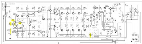
To my question, I have looked at this thread, and I have looked at the following modell schematics of my amp (RB-1582). The 1582 has the exact same topology with some resistance and capitance value changes.
My plan is to execute these exact same modifications to my 1080, as that looks like I would probably lower the gain by 3db
Questions regarding this thread
1. If I make these changes marked in the 1582 schematic picture attached, compared with the 1080 schematic attached - is it adviseable to remove the 33k / R603 aswell and just keep the 100pf cap where it is? Without making the CM modification as that seems a bit too much at the moment.
2. The 22R resistors on the output transistor bases - are they necessary/whats the function of adding these? Can't remember anything in this thread about such resistance needed.
3. Are these modifications within the safe operational limit or is it something else in the new 1582 circuit that I might have missed out on?
Thank you very much in advance, if anyone cares to answer, that is!
1. The gain/input sensitivity is too high for me
2. Would love to make some minor changes for the better of the performance - mostly because it's possible and I love to try it out.
I have done schematic modifications before but only on preamps and turntables, hence this will be my first attempt on a power amp.
To my question, I have looked at this thread, and I have looked at the following modell schematics of my amp (RB-1582). The 1582 has the exact same topology with some resistance and capitance value changes.
My plan is to execute these exact same modifications to my 1080, as that looks like I would probably lower the gain by 3db
Questions regarding this thread
1. If I make these changes marked in the 1582 schematic picture attached, compared with the 1080 schematic attached - is it adviseable to remove the 33k / R603 aswell and just keep the 100pf cap where it is? Without making the CM modification as that seems a bit too much at the moment.
2. The 22R resistors on the output transistor bases - are they necessary/whats the function of adding these? Can't remember anything in this thread about such resistance needed.
3. Are these modifications within the safe operational limit or is it something else in the new 1582 circuit that I might have missed out on?
Thank you very much in advance, if anyone cares to answer, that is!
Attachments
Hi Mikael,
I am struggling a bit to understand exactly what you have done - and/or what you would like to do. But I guess:
A) You are looking at changing stuff in the RB-1080 - inspired by the RB-1582 amp schematics?
B) You want to reduce the gain by 3dB?
Assuming yes, let's go on.
You can't just remove the 33k, it it needed for the bias dc currents from Q601/Q607. You can change it to 12k as in the 1582, more on that below.
The 22R's are just base resistors and do not affect the gain. The 100pF cap is a HF input quencher and should also be left in.
You have marked C605 (is it actually mounted in the amp?), anyway, it is for HF stability and has probably been superseded by C627 and R665.
If you reduce the R603 33k to 12k, you will get a reduction in gain, but only by about 0.4dB and the LF roll-off point will increase from 1Hz to 2.8Hz.
To reduce the gain by 3dB you instead need to reduce the value of the feedback resistor R657. So in the 1080, change the 15k4 to 11k.
Or, change both to 12k - that will give you (almost) -3dB - and a bonus that the speaker output offset should drop to a few mV.🙂
Hope this helps,
Best,
Per
Hi Per,
Thank you for your quick reply!
Yes that is exactly what I was trying to express! 🙂 The base resistors though is the only ones I do not have at home. That's why I was wondering about the necessity of them. And If it is safe to just do all of these modifications without anything else?
What about changing both the feedback resistor and the bias one to 10kohm? Would that hit the 3db? I would rather love to get the amp down to 20db from 29 but that would be a bit too challenging I guess.
There is a 220p at C605 and 470ohm at R605. Also the R663 to ground will be redundant after the 1582 implementation. Will these alter the sound away from the "rotel" sound? I would appreciate a cleaner? sound
Thank you for sharing your knowledge!
//Mikael
Hi Mikael,
If you change the input (not the bias) resistor R603 and the NFB resistor R657 to 10k, you will get a ~4dB gain reduction, but the LF roll-off goes up to 3.4Hz.
To get 20dB gain, you need to change R657 to 5k36, and either keeping R603 at 12k or increasing C601 to 15-22uF or higher.
None of the other changes you are suggesting will alter the sound, so my best advice is to keep them all as they are.
"Upgrading" requires a very good understanding of how the circuits work.
Going in 'blind' can often make things worse - and even more often end in tears.😢 (And I speak from painful experience!)
Per
Hi Mikael,
I hope that I didn't put you off or in any way dent your interest in upgrading, that was definitely not my intention.
I have had a look at the tech manual of the RB-1080 and it looks (almost) identical to the RB-991s which Smartdriver upgaded.
So, if you are interested, I can send you the instructions on how and where to put in emitter followers and Miller capacitors. And what to remove.
That will change the sound of the amp - just see post #393, 394 and 446.
Please note that it requires you to cut tracks, drill holes and make absolutely sure that the components go in the right way and in the right places, etc.
Remember, these amps operate under almost 150V rails and a huge reservoir capacitor bank (in fact a "Mini Chernobyl") and any mistake or accidental shorting will be punished before you can react.
I would strongly suggest that you take the main pcb's out, add some simple heat sink to the power transistors - and do the work under +/-30V power from a pair of lab supplies with current limiters.
And note that the the work will be completely at your own responsibility - not mine.😇
Best,
Per
Hi Per,
Not at all. But thank you for thinking about me. Been busy testing various feedback levels in spice. A bit reluctant to try on the amp as I don't have any large enough resistors or a dummy load to use the generator and scope.
I have read those posts over and over 😉 Thinking about it. But I do also have a couple of 100's of 992s and 1845s from my pre-amp projects, So I thought I might just match them and put them together with paste and shrink tube.
I also really need to lower the gain which is way too high for my taste. But just increasing the feedback from 15,4k ohm to 12k, looks like rotel found it to be somewhat unstable as they added the base stoppers/resistors to mitigate that (I guess) - but simulating with base resistors doesnt do any good to the perfomance - rather the other way around. Hence I would prefer to not add those. Thinking I would just put ferrite beads on the base pins should give about the same effect - though of course a bit more difficult to size them accordingly.
They have also moved the zobel to before the output relay which I do like and intend to do the same - I guess that would prevent self oscillation even if the relay is open or closed. Then I'm a bit confused about the additional zobel at the output. why use two, maybe that is just a fault in the schematic.
I also looked at the scematics for the larger 1090 - and that one has the usual L//R filter at the output aswell as lower resistance base resistors to prevent oscillation. So now I'm really confused if I also should add a small L//R filter at the output (maybe 0,5uh in parallel with a 6ohm 5w mox) just to be sure.
When I have done all these things, and the amp survived, I will most likely go for the current mirror and miller caps. knowing myself to well.
Have anyone here experienced any unstable effects of higher feedback in these topologies?
//Mikael
Last edited:
Hi Per,
I read the smartdriver posts again.
Wondering if the "rotel-lag" change is applicable on the 1080 aswell? Though it doesnt have the 33k resistor it has a 330p cap. Would changing that to a lower value cap combined with a miller comp cap of 100p on one of the vas be a better option or would it matter at all for the stability?
My VAS are also running very hot so I'll measure them and increase their emittor resistors as you/smartdriver did.
Contemplating on hardwiring the main psu caps channel individually instead of the main copperplate. But would that even make a difference in reality?
I'm not so worried about brands and "hifi" components, maybe I should be, but the mouser and digikey stuff have been enough for me. Noticed a lot of focus on those things in those smartdriver posts.
//M
Hi Mikael,
Yes, the changes to the 991 are applicable to the 1080. Same problems as Smartdriver had.
The VAS current is way too high (particularly with the EFs that follow before the drivers), and so the poor VAS transistors are boiling.
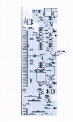
I enclose the amended schematic showing what to do.
Fitting the VAS emitter followers is the tricky part, I enclose a pair of pcb drawings that shows what we physically did.
Please note that you will have to very closely check whether there may be any differences between the 991 and the 1080, I haven't done that.
Per
Yes, the changes to the 991 are applicable to the 1080. Same problems as Smartdriver had.
The VAS current is way too high (particularly with the EFs that follow before the drivers), and so the poor VAS transistors are boiling.
I enclose the amended schematic showing what to do.
Fitting the VAS emitter followers is the tricky part, I enclose a pair of pcb drawings that shows what we physically did.
Please note that you will have to very closely check whether there may be any differences between the 991 and the 1080, I haven't done that.
Per
Attachments


Thank you!
It looks like it might be possible on my pcb to just lift the leg on the VAS and connect the EF there without cutting the trace. Need to look into that more carefully. Why did you relocate the R607, due to space?
What are your thoughts on higher feedback - lower gain vs stability? Not too keen on those base stoppers on the output trannies. Might experiment a bit with a couple of ferrite beads but a bit sceptic to that result. But I really would enjoy the lower gain. referring to the changes made to the 1582 modell vs these.
//Mikael
The relocation of R607 is indicated on the pcb layout pics.
I can't see why lower gain should lead to any instability, actually on the contrary.
Per
I can't see why lower gain should lead to any instability, actually on the contrary.
Per
Yes. I noticed the relocation, just wondered why it was done.
I had the understanding that too much negative feedback may lead to oscillation in the high frequencies, and that high speed transistors like these sankens could be victims of that, and that would explain the adding of base resistors to the output transistors in the 1582 vs 1080 due to the increased feedback. But I'm far from an expert. So that was just my understanding of the schematic.
Anyways I was wondering how these changes with the extra emitter followers and miller caps would turn out for the stability. Would it be better or worse? or the same?
//Mikael
Hi again,
Just a quick question to be 100% sure. This is connected to signal ground?

And again thank you very much for this exciting mod!!
It does look like I might be able to pull it off without cutting traces, maybe just two new holes, that's not too bad 🙂
//M
Just a quick question to be 100% sure. This is connected to signal ground?
And again thank you very much for this exciting mod!!
It does look like I might be able to pull it off without cutting traces, maybe just two new holes, that's not too bad 🙂
//M
- Home
- Amplifiers
- Solid State
- Improve a Rotel amp THD by 20dB!