Hi Per!
Good explanations. I normally sit back and let you do your thing.
For the differential complimentary diff pair, matching each PNP and NPN pair is critical, and the closer the pairs are, the better the performance is - and DC stability. You don't need a servo with well matched and designed diff pairs, or the complimentary style. It is important to thermally connect and isolate each pair. They must track temperature. If you can connect the two pairs thermally - even better! But it isn't the end of the world if you can't see to do that.
-Chris

Susan is a skilled designer, she does know what she is doing. Read her design goals and you'll understand why she does what she does. Nelson Pass is the same way, his goals aren't along the same lines as is common.
I don't doubt that she is very skilled. But I am still not sold on output transformers in the signal path of HiFi gear.
My first amp was a Fisher TX-100 (second (read: fifth) hand). Tube amp circuit topology using transistors instead of tubes.
I was very proud of it, but a basic SPL measurement showed that it rolled off badly already from 10kHz and up. It really didn't bother me at the time, as my only sound source was a Revox A-77 with a worn playback head and the speakers were my home built Voight horns with the cheapest Philips "basket cage" 8" full range driver. But the combination often got me 'invited' to some of the best parties with the prettiest girls....😉
I recently repaired a Rogers Ravensbourne for a friend. It is a UK classic amp which again uses an output transformer after the power transistors. I do appreciate the engineering and workmanship of the time, but it is a bit of a stretch to call it a HiFi amp. And it was a b*tch to get the offset adjusted on.
Per
Last edited:
Hi Per!
Good explanations. I normally sit back and let you do your thing.
For the differential complimentary diff pair, matching each PNP and NPN pair is critical, and the closer the pairs are, the better the performance is - and DC stability. You don't need a servo with well matched and designed diff pairs, or the complimentary style. It is important to thermally connect and isolate each pair. They must track temperature. If you can connect the two pairs thermally - even better! But it isn't the end of the world if you can't see to do that.
-Chris
Totally agree.
Per
Hi Per,
I'm not a fan of transformers unless they are E-I designs for power transformers or RF designs. They are problematic for phase shift and various distortion mechanisms.
But they can be used to obtain a certain sound or for other reasons.
I'm not a fan of transformers unless they are E-I designs for power transformers or RF designs. They are problematic for phase shift and various distortion mechanisms.
But they can be used to obtain a certain sound or for other reasons.
Double Differential Input Push-Pull EF-VAS Bias Revisited
So, with LTP current mirrors in place, things get far worse as the VAS and bias current is no longer controlled. This is because the voltage V(?) at the high impedance connection between the LTP and current mirror collectors is floating – it can (almost) be anywhere between the rail voltage and ground and it is normally drifting slightly up and down with the temperature of the connected transistors.

And with no second current source or forward control, the VAS and/or amplifier will drift from no bias current to eventually go up in smoke – and I speak from experience.
When the VAS current starts to increase as its base voltage drifts towards ground, this can suddenly avalanche faster than you can measure (or indeed react to) due to the self-destructive positive thermal runaway effect in BJT’s (more current – hotter junctions and hotter junctions – even more current).
By now, I have probably murdered more KSA992/KSC1845 SOT-23’s than most people. And some TO-92's.😳
So, something needs to be done to define the VAS/ bias current.
A few contributors on this thread has suggested solutions and there is more in the literature.
I started out by studying Self and Cordell on the issue. Self describes and discusses the difficulties and his conclusion is that ’more research is needed’ and that he ’definitely prefers the single-ended VAS topology.’
Ok, I don’t disagree, but that is sort of limited help when you have an RA-971 sitting on the workbench for an upgrade.
Bob Cordell suggests a seemingly elegant solution in his brilliant book ’Designing Audio Power Amplifiers’, I enclose a part of the schematic (hoping that I don’t get into any copyright problems) showing the addition of a ’helper transistor’ Q14 and two resistors R15/16 to the current mirror.

I believe that it is actually an old circuit trick from IC opamp designs, and as I understand it, the Q13/14 ’helpers’ increases the balance and equality of the mirror currents and the 47k resistors between the LTP collectors should ensure that their voltages remain the same, thereby allegedly defining the base voltage at the VAS’s.
So, I built this exact circuit into the RA-971 on the bench and can testify that - it doesn’t work. At least not in the Rotel.
It stopped the thermal runaway blue smoke destruction of the VAS, but there was no bias current and the output power stage never turned on. The resistors between the LTP collectors had to be reduced to less than 6k before the VAS transistors even started to wake up.
(I noted that Cordell later in his 2016 Burning Amp talk had changed the values of these resistors by a factor 10 (!), so the 47k was now 4k7 and the 1k had been increased to 10k).
I tried those values as well, but the control of the VAS and bias current was still found wanting and subject to VAS temperature variations.
Add to that the unwanted loading and reduction in transconductance of the LTP input stage.
Maybe someone more knowledgeable than me could comment on these findings?
Searching for more stable solutions, I considered (and tried some) other circuits including servo circuits, I know servos can be made to work well, but all complicated the upgrade work significantly, as did suggestions of more current mirror strings/stages in the circuit.
Remember, my goal throughout this thread has been to provide relatively easy drop-in replacement upgrades for the existing component layout on the Rotel pcb – at least as far as possible. Putting in rats-nest circuits with untidy airwires flying everywhere does not meet that objective, IMHO.
So the search continued and has now been going on (well, on and mostly off) for two years.
Most sane people would by now have left it for others to ’research’ and solve, but I am obviously not in the ’sane’ category.😊
TBC
Per
So, with LTP current mirrors in place, things get far worse as the VAS and bias current is no longer controlled. This is because the voltage V(?) at the high impedance connection between the LTP and current mirror collectors is floating – it can (almost) be anywhere between the rail voltage and ground and it is normally drifting slightly up and down with the temperature of the connected transistors.
And with no second current source or forward control, the VAS and/or amplifier will drift from no bias current to eventually go up in smoke – and I speak from experience.
When the VAS current starts to increase as its base voltage drifts towards ground, this can suddenly avalanche faster than you can measure (or indeed react to) due to the self-destructive positive thermal runaway effect in BJT’s (more current – hotter junctions and hotter junctions – even more current).
By now, I have probably murdered more KSA992/KSC1845 SOT-23’s than most people. And some TO-92's.😳
So, something needs to be done to define the VAS/ bias current.
A few contributors on this thread has suggested solutions and there is more in the literature.
I started out by studying Self and Cordell on the issue. Self describes and discusses the difficulties and his conclusion is that ’more research is needed’ and that he ’definitely prefers the single-ended VAS topology.’
Ok, I don’t disagree, but that is sort of limited help when you have an RA-971 sitting on the workbench for an upgrade.
Bob Cordell suggests a seemingly elegant solution in his brilliant book ’Designing Audio Power Amplifiers’, I enclose a part of the schematic (hoping that I don’t get into any copyright problems) showing the addition of a ’helper transistor’ Q14 and two resistors R15/16 to the current mirror.
I believe that it is actually an old circuit trick from IC opamp designs, and as I understand it, the Q13/14 ’helpers’ increases the balance and equality of the mirror currents and the 47k resistors between the LTP collectors should ensure that their voltages remain the same, thereby allegedly defining the base voltage at the VAS’s.
So, I built this exact circuit into the RA-971 on the bench and can testify that - it doesn’t work. At least not in the Rotel.
It stopped the thermal runaway blue smoke destruction of the VAS, but there was no bias current and the output power stage never turned on. The resistors between the LTP collectors had to be reduced to less than 6k before the VAS transistors even started to wake up.
(I noted that Cordell later in his 2016 Burning Amp talk had changed the values of these resistors by a factor 10 (!), so the 47k was now 4k7 and the 1k had been increased to 10k).
I tried those values as well, but the control of the VAS and bias current was still found wanting and subject to VAS temperature variations.
Add to that the unwanted loading and reduction in transconductance of the LTP input stage.
Maybe someone more knowledgeable than me could comment on these findings?
Searching for more stable solutions, I considered (and tried some) other circuits including servo circuits, I know servos can be made to work well, but all complicated the upgrade work significantly, as did suggestions of more current mirror strings/stages in the circuit.
Remember, my goal throughout this thread has been to provide relatively easy drop-in replacement upgrades for the existing component layout on the Rotel pcb – at least as far as possible. Putting in rats-nest circuits with untidy airwires flying everywhere does not meet that objective, IMHO.
So the search continued and has now been going on (well, on and mostly off) for two years.
Most sane people would by now have left it for others to ’research’ and solve, but I am obviously not in the ’sane’ category.😊
TBC
Per
Last edited:
HI thank you for the very kind and valuable adviceHI Gino,
1) No.
The DDiPPVAS looks very nice on the schematic with everything beautifully balanced and mirrored etc, but getting excellent performance is (among other things) relying on finding transistor pairs of closely matching properties - particularly between NPN and PNP devices.
And the specs that are obtainable from both these topologies are very similar. Any audible differences? Hmm.. maybe, but I haven't done any blind A/B test.
2) I don't think it is that simple.
Yes, I also prefer low component count designs (Hiraga's 'Le Monstre' is a fine example), but it is a class A amp and so I believe are most of Pass' low component designs(?). In the lower idle power class AB/B there are a number of non-linear issues that need more added components to straighten out.
Per
I have cleared my mind a lot I asked became if I am not wrong the best preamps from Rotel are discrete and have all double differential input pairs
From this my curiosity
For point 2 if not big power is needed maybe class A could be a viable option?
Double Differential Input Push-Pull EF-VAS Bias Revisited
A better solution would perhaps be to somehow place a stable current source inside or around the bias voltage circuit between the two VAS’s, but all designs ideas that I have considered in and around the VAS/Bias string eventually fall short for a variety of reasons including the basic fact that current sources are high impedance whereas the bias circuit is essentially equivalent to a resistor of a couple of hundred ohms.
Chalky suggested (post #433) a seemingly elegant solution for current control inside the VAS module which I recently decided to revisit and eventually try out in practice.

The VAS transistor now (also) form half of an internal current mirror with an extra transistor with external setting of the mirror current.
But it first met the other unfortunate restrictions in my ’drop-in’ replacement objective: Available size and temperature control of the modules.
The modules are intended as drop-ins for a TO-126 or TO-220 sized VAS transistor, so I can’t go much beyond a10x15 mm pcb. Further, the onboard SOT-23 SMD transistors have a max dissipation of 350mW, so when the rail voltages go to e.g. 50V you reach that limit with a 6-7mA VAS current (and these small devices do heat up unnervingly quickly). And Rotel rarely used - or even made space for any heat sink on the VAS transistors.
However, I thought these issues could most probably be sorted out - somehow.
But unfortunately - this design idea didn't work.
While the VAS transistor current is now well defined by the extra current mirror transistor, you have no control of the current in the PNP emitter follower – and consequently the total bias stage current. And, you guessed it...more blue smoke ensued.
So, back to the drawing board….🤔
TBC,
Per
A better solution would perhaps be to somehow place a stable current source inside or around the bias voltage circuit between the two VAS’s, but all designs ideas that I have considered in and around the VAS/Bias string eventually fall short for a variety of reasons including the basic fact that current sources are high impedance whereas the bias circuit is essentially equivalent to a resistor of a couple of hundred ohms.
Chalky suggested (post #433) a seemingly elegant solution for current control inside the VAS module which I recently decided to revisit and eventually try out in practice.
The VAS transistor now (also) form half of an internal current mirror with an extra transistor with external setting of the mirror current.
But it first met the other unfortunate restrictions in my ’drop-in’ replacement objective: Available size and temperature control of the modules.
The modules are intended as drop-ins for a TO-126 or TO-220 sized VAS transistor, so I can’t go much beyond a10x15 mm pcb. Further, the onboard SOT-23 SMD transistors have a max dissipation of 350mW, so when the rail voltages go to e.g. 50V you reach that limit with a 6-7mA VAS current (and these small devices do heat up unnervingly quickly). And Rotel rarely used - or even made space for any heat sink on the VAS transistors.
However, I thought these issues could most probably be sorted out - somehow.
But unfortunately - this design idea didn't work.
While the VAS transistor current is now well defined by the extra current mirror transistor, you have no control of the current in the PNP emitter follower – and consequently the total bias stage current. And, you guessed it...more blue smoke ensued.
So, back to the drawing board….🤔
TBC,
Per
Hi Gino,
Yes, you can indeed get absolutely great audio enjoyment from a class A amp.
The trouble with even an 8 Watt 'Le Monstre' is to manage the idle heat produced in class A.
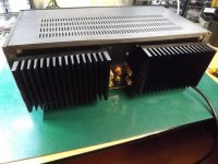
I have two JP Hiragas (both home built on a shoestring budget, of course). One (built into an old Sansui A-40 case) has big passive heatsinks, see pic.
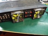
The other is built into a smaller Pioneer SA-410 case using CPU heatsinks cooled by two fans at the rear.
Mind you, I went through a lot of 80mm fans to finally find some (and a way of driving them) that didn't have an audible buzz or whizz.
But both amps now keep the heatsinks at touchable temperatures.
And they do sound outstandingly wonderful!
I now sometimes use them as comparison 'yardstick' for my Rotel upgrades.
Per
For point 2 if not big power is needed maybe class A could be a viable option?
Yes, you can indeed get absolutely great audio enjoyment from a class A amp.
The trouble with even an 8 Watt 'Le Monstre' is to manage the idle heat produced in class A.
I have two JP Hiragas (both home built on a shoestring budget, of course). One (built into an old Sansui A-40 case) has big passive heatsinks, see pic.
The other is built into a smaller Pioneer SA-410 case using CPU heatsinks cooled by two fans at the rear.
Mind you, I went through a lot of 80mm fans to finally find some (and a way of driving them) that didn't have an audible buzz or whizz.
But both amps now keep the heatsinks at touchable temperatures.
And they do sound outstandingly wonderful!
I now sometimes use them as comparison 'yardstick' for my Rotel upgrades.
Per
Attachments
How about take two dead unit’s power transformers and put them back to back, use them as (an) isolation transformer(s).
Probably help with the 50/150hz garbage.
Probably help with the 50/150hz garbage.
A very interesting thread. Sometimes there's lack of transparency about subtle design choices made by engineers that may nor may not make a difference. Strangely this is a good design that will work well. There are many solutions that work the same way but look superficially different that engineers come up with to solve the same problem. Creativity was fueled by patenting and pressure from marketing as well as the need to distinguish products resulting in different designs to achieve the same thing, thus audio engineers became artists, contortionists and magicians. Interestingly output stages didn't change much. A good post Ostripper. Indeed as this thread has noted some mods worked, others made things worse, others had no apparent benefit. There's some boundary between theory and ground truth. A good thread👍Typical 3 stage gain "Sansui type" High Ft classic amp.
What is weird , they use a phase inverted driver stage (diamond like)
and then use positive feedback.
(below)
The NFB version of this amp (sansui) . is typically 20ppm-20k.
That is , with faster 35mhz sanken outputs.
OS
How about take two dead unit’s power transformers and put them back to back, use them as (an) isolation transformer(s).
Probably help with the 50/150hz garbage.
Yeah, I thought about that and I know I have a large autotransformer somewhere in the garage.
Question is where?🤔
Double Differential Input Push-Pull EF-VAS Bias Revisited
Firstly, a general warning: You should not do upgrade circuit experiments like this in a working amplifier.
Well actually, you can, but at your peril. You will very soon find out how much ’oomph’ there is in those big reservoir capacitors long after you’ve panic hit the off switch!
Therefore, I chose to breadboard one of the LTP-CM-EF-VAS halves on a plug-in ’fumbleboard’, well supervised and current limited by two bench power supplies and as many DMM’s I could hook up.

After the usual stupid flying wire connection mistakes, I got a stable VAS current in a variation of Chalky’s original idea in which I ditched the last PNP emitter follower and instead used a parallel pair of VAS transistors to keep the heat dissipation of each in check.
Because of the promising results I decided to CAD things up only to find that I was out of real estate on the VAS module pcb - and I couldn’t place a traditional current source onto it without making the module too big – or production very difficult indeed.
I could just fit one more SOT-23 and maybe squeeze in one more 0603 resistor, so I first thought of using the trusted old LM334 (which, BTW itself is a class act in clever use of current mirrors - if you're into that thing). But I soon learned that it was not available in SOT-23 – at least I couldn’t find any or indeed anything comparable.
Fortunately, there are now mA LED drivers in SOT-23 packages and I chose the NCR401.
It is basically a classic 'two diode / one transistor' 10mA (nominal) current source - all on a chip. Which means that it should theoretically also be lower noise than more complicated current regulators. And no extra resistor is needed.😌
One drawback is that it can’t take an amp’s 50V+ rail voltages, so I decided that a drop resistor in the ground wire would be acceptable, whereby it only ’sees’ about 15V. And a second was that it has no adjustment option to get a lower current, so I had to work with the 9mA.
The circuit I finally decided to have made into VAS11 pcb modules looked like this:
(yes, you read that correctly....VAS11 (!) - there has indeed been quite a few ideas and iterations since VAS3 and 4 over time)


All transistors are KSC1845 (or rather FJV1845). The NCR401 sources 9mA and the differences in emitter resistor values should give a VAS current of 3mA through each of the VAS transistors, 6mA in total. At least in theory.
The external resistor (4k for 50V rails) at the top drops the voltage by 35V (so it should be a 1/2 W or 1W type - and it does get hot!).
But VAS module dissipation is quite well spread out over the pcb and less than 400mW total.
So, did it work?
Well, not exactly as planned….😳
TBC
Firstly, a general warning: You should not do upgrade circuit experiments like this in a working amplifier.
Well actually, you can, but at your peril. You will very soon find out how much ’oomph’ there is in those big reservoir capacitors long after you’ve panic hit the off switch!
Therefore, I chose to breadboard one of the LTP-CM-EF-VAS halves on a plug-in ’fumbleboard’, well supervised and current limited by two bench power supplies and as many DMM’s I could hook up.
After the usual stupid flying wire connection mistakes, I got a stable VAS current in a variation of Chalky’s original idea in which I ditched the last PNP emitter follower and instead used a parallel pair of VAS transistors to keep the heat dissipation of each in check.
Because of the promising results I decided to CAD things up only to find that I was out of real estate on the VAS module pcb - and I couldn’t place a traditional current source onto it without making the module too big – or production very difficult indeed.
I could just fit one more SOT-23 and maybe squeeze in one more 0603 resistor, so I first thought of using the trusted old LM334 (which, BTW itself is a class act in clever use of current mirrors - if you're into that thing). But I soon learned that it was not available in SOT-23 – at least I couldn’t find any or indeed anything comparable.
Fortunately, there are now mA LED drivers in SOT-23 packages and I chose the NCR401.
It is basically a classic 'two diode / one transistor' 10mA (nominal) current source - all on a chip. Which means that it should theoretically also be lower noise than more complicated current regulators. And no extra resistor is needed.😌
One drawback is that it can’t take an amp’s 50V+ rail voltages, so I decided that a drop resistor in the ground wire would be acceptable, whereby it only ’sees’ about 15V. And a second was that it has no adjustment option to get a lower current, so I had to work with the 9mA.
The circuit I finally decided to have made into VAS11 pcb modules looked like this:
(yes, you read that correctly....VAS11 (!) - there has indeed been quite a few ideas and iterations since VAS3 and 4 over time)
All transistors are KSC1845 (or rather FJV1845). The NCR401 sources 9mA and the differences in emitter resistor values should give a VAS current of 3mA through each of the VAS transistors, 6mA in total. At least in theory.
The external resistor (4k for 50V rails) at the top drops the voltage by 35V (so it should be a 1/2 W or 1W type - and it does get hot!).
But VAS module dissipation is quite well spread out over the pcb and less than 400mW total.
So, did it work?
Well, not exactly as planned….😳
TBC
Last edited:
HI thank you for very much again The only class A amp i listened to was a Krell ksa100 many years ago and i like it a lot But too expensive to buy for me I wonder if class A is mandatory to get really great soundHi Gino,
Yes, you can indeed get absolutely great audio enjoyment from a class A amp.
The trouble with even an 8 Watt 'Le Monstre' is to manage the idle heat produced in class A.
I have two JP Hiragas (both home built on a shoestring budget, of course). One (built into an old Sansui A-40 case) has big passive heatsinks, see pic.
The other is built into a smaller Pioneer SA-410 case using CPU heatsinks cooled by two fans at the rear.
Mind you, I went through a lot of 80mm fans to finally find some (and a way of driving them) that didn't have an audible buzz or whizz.
But both amps now keep the heatsinks at touchable temperatures.
And they do sound outstandingly wonderful!
I now sometimes use them as comparison 'yardstick' for my Rotel upgrades.
Per
Hi Gino,
Class A sounds absolutely great, but yes they are normally very expensive.
An upgraded APS Rotel comes pretty close, IMHO (but I might be slightly biased).😉
If 8W is enough for you (ie. because you have effective speakers) I could consider selling you one of my two Le Monstre prototypes, or, depending your soldering and mechanical skills, a pair of my Monstre pcb's and get on the DIY bandwagon?
PM me if you would like to discuss further. No pressure.
Per
Last edited:
The circuit I finally decided to have made into VAS11 pcb modules looked like this:
(yes, you read that correctly....VAS11 (!)- there has indeed been quite a few ideas and iterations since VAS3 and 4 over
😱 Holy s**t
When you dig in, you dig in good

Double Differential Input Push-Pull EF-VAS Bias Revisited
I got so carried away with optimism over the promising VAS results that I skipped the safe but tedious breadboarding of the design and, yes - I went straight ahead and put the modules right into the RA-971 (in clear violation of my own principles of caution and proper due diligence).
The result was of course inevitable – blue smoke (but not from a cigar).
A bit (ok, very) disillusioned and disgusted, I put the project on the shelf for... (cough)… a number of months (read: a year).
⏳/😶/
But ok, I was kept busy repairing and upgrading a seemingly never ending stream of RA-800/900 series, RA 01’s to 05’s, but also some DDiPPVAS amps like RA/RB971/980/991’s.
Although in these, I decided to forget all about using a LTP current mirror and kept the existing LTP collector resistor and VAS transistor while finding the best place on the pcb to put a discrete TO-92 EF in front of it.
Admittedly, this works very well indeed, but it is fiddly and requires track cutting, drilling and scraping solder pads plus strict concentration to get absolutely right – not easy DIY stuff, imho.
And of course we all would ultimately like to ’up the ante’ with current mirror modules.🙏
Speaking of which, I made a new CM2 version of the LTP current mirror module, making them into improved Wilson mirrors, further improving linearity:


Using two BCM847 matched transistor pairs greatly simplifies the need device selection for parameter matching and is really little more effort than making the old CM1.
With 2mA through each LTP collector, the voltage across the mirror is 1.5V, so the BCM’s have no problem operating within high voltage rail amps.
(You may note that I actually also made space for a resistor between the LTP collectors – in case I was wrong in outright discarding the ’helper transistor’ solution. You see, being wrong is not an uncommon trait of mine).
These CM2 current mirrors work perfectly, giving a better current balance for the LTPs to enjoy and do the ’voodoo that they do so well’.
TBC
I got so carried away with optimism over the promising VAS results that I skipped the safe but tedious breadboarding of the design and, yes - I went straight ahead and put the modules right into the RA-971 (in clear violation of my own principles of caution and proper due diligence).
The result was of course inevitable – blue smoke (but not from a cigar).
A bit (ok, very) disillusioned and disgusted, I put the project on the shelf for... (cough)… a number of months (read: a year).
⏳/😶/
But ok, I was kept busy repairing and upgrading a seemingly never ending stream of RA-800/900 series, RA 01’s to 05’s, but also some DDiPPVAS amps like RA/RB971/980/991’s.
Although in these, I decided to forget all about using a LTP current mirror and kept the existing LTP collector resistor and VAS transistor while finding the best place on the pcb to put a discrete TO-92 EF in front of it.
Admittedly, this works very well indeed, but it is fiddly and requires track cutting, drilling and scraping solder pads plus strict concentration to get absolutely right – not easy DIY stuff, imho.
And of course we all would ultimately like to ’up the ante’ with current mirror modules.🙏
Speaking of which, I made a new CM2 version of the LTP current mirror module, making them into improved Wilson mirrors, further improving linearity:
Using two BCM847 matched transistor pairs greatly simplifies the need device selection for parameter matching and is really little more effort than making the old CM1.
With 2mA through each LTP collector, the voltage across the mirror is 1.5V, so the BCM’s have no problem operating within high voltage rail amps.
(You may note that I actually also made space for a resistor between the LTP collectors – in case I was wrong in outright discarding the ’helper transistor’ solution. You see, being wrong is not an uncommon trait of mine).
These CM2 current mirrors work perfectly, giving a better current balance for the LTPs to enjoy and do the ’voodoo that they do so well’.
TBC
Hi thank you again for the very helpful advice and offerHi Gino,
Class A sounds absolutely great, but yes they are normally very expensive.
An upgraded APS Rotel comes pretty close, IMHO (but I might be slightly biased).😉
If 8W is enough for you (ie. because you have effective speakers) I could consider selling you one of my two Le Monstre prototypes, or, depending your soldering and mechanical skills, a pair of my Monstre pcb's and get on the DIY bandwagon?
PM me if you would like to discuss further. No pressure.
Per
at present i am looking for a little workshop where to start doing something
I am more intrigued by the restoration of old units
I saw a video of an amp full or topsoil and dirt then cleaned up and ending in a shiny look
i was very impressed
another amp that i like was a Sugden
i find strange that nobody is interested to clone little power class A with great sound
i have found a schematic of the Sugden and it does not look very complex
another thing that i have learnt is that for low power amps lower rail voltages are better because allow for a greater current delivery of the output transistors in safe operating conditions
to end an idea would be to gut an old low power amp
increase its power supply
redesign the heat sink and
cranck up its bias to make it work in class A
even a cheap Rotel ra820 could be a good base for that task
Last edited:
Hi thanks a lot again I am going to cut the board with a dremel and take out only what i need i.e. the amplifying circuits
I could use beefier output pairs But the big job will be done i guess
Kindest regards,
gino 🙂👍
I could use beefier output pairs But the big job will be done i guess
Kindest regards,
gino 🙂👍
Double Differential Input Push-Pull EF-VAS Bias Revisited
To complement the improvement by the new CM2 mirrors, I also decided to put in emitter degrading resistors in the LTPs.
Now, ”degrading” sound like the opposite to ”upgrading”, but it is actually a brilliant idea (and excellently described by D. Self in ’Audio Amplifier Design’).
From memory it reads:
All transistors have a finite collector to emitter resistance, roughly equal to 25/Ic (in mA). So, eg. for a 1mA current, this internal resistance is 25 ohms.
Unfortunately it is not linear, leading to added distortion.
Adding resistors to the emitters of course increases the total resistance, but discrete resistors are linear. So, putting in 25 ohm ”degrading” resistors but then increasing the current through the LTP to, say, 2mA - we have replaced 25 ohm of non-linear internal resistance with a linear.
And increasing LTP current (while carefully minding their temperatures) has a second advantage as it provides more current to faster (dis-)charge the Miller capacitors, giving a faster amplifier slew rate.
(You can also see such resistors used in Cordell's schematic in post #825)

And speed up it does. This trace is from a RA-931 fed with a square wave, showing the difference in the speed of the signal response (Slew Rate) before and after adding the emitter degrading resistors. In fact, it now has a small overshoot which doesn’t look good on paper, but we don’t normally play square waves through the amps, so it is probably of limited concern.
But if needed, it is easy to correct by increasing the HF rejection 100pF PP capacitor from the LTP input base to ground - to eg. 150pF.
However, physically fitting in these emitter resistors are again quite fiddly.
So, to follow my goal of making things easier for my fellow DIY’ers (and chiefly, myself), I decided to take the fiddle out of the performance by making…....(drum roll)🥁…. Heatshrink-Wrapped-Pre-Mounted-Emitter-Resistor-Close-Matched-Transistor-LTP-Units.
(Still working on the acronym 😊).

These units are now simple direct drop-in replacements for the LTPs on the pcb.
Thus armed with a improved front end setup – was it then time for a final courageous frontal attack on the stubborn VAS modules?
Stay tuned to find out....
To complement the improvement by the new CM2 mirrors, I also decided to put in emitter degrading resistors in the LTPs.
Now, ”degrading” sound like the opposite to ”upgrading”, but it is actually a brilliant idea (and excellently described by D. Self in ’Audio Amplifier Design’).
From memory it reads:
All transistors have a finite collector to emitter resistance, roughly equal to 25/Ic (in mA). So, eg. for a 1mA current, this internal resistance is 25 ohms.
Unfortunately it is not linear, leading to added distortion.
Adding resistors to the emitters of course increases the total resistance, but discrete resistors are linear. So, putting in 25 ohm ”degrading” resistors but then increasing the current through the LTP to, say, 2mA - we have replaced 25 ohm of non-linear internal resistance with a linear.
And increasing LTP current (while carefully minding their temperatures) has a second advantage as it provides more current to faster (dis-)charge the Miller capacitors, giving a faster amplifier slew rate.
(You can also see such resistors used in Cordell's schematic in post #825)
And speed up it does. This trace is from a RA-931 fed with a square wave, showing the difference in the speed of the signal response (Slew Rate) before and after adding the emitter degrading resistors. In fact, it now has a small overshoot which doesn’t look good on paper, but we don’t normally play square waves through the amps, so it is probably of limited concern.
But if needed, it is easy to correct by increasing the HF rejection 100pF PP capacitor from the LTP input base to ground - to eg. 150pF.
However, physically fitting in these emitter resistors are again quite fiddly.
So, to follow my goal of making things easier for my fellow DIY’ers (and chiefly, myself), I decided to take the fiddle out of the performance by making…....(drum roll)🥁…. Heatshrink-Wrapped-Pre-Mounted-Emitter-Resistor-Close-Matched-Transistor-LTP-Units.
(Still working on the acronym 😊).
These units are now simple direct drop-in replacements for the LTPs on the pcb.
Thus armed with a improved front end setup – was it then time for a final courageous frontal attack on the stubborn VAS modules?
Stay tuned to find out....
- Home
- Amplifiers
- Solid State
- Improve a Rotel amp THD by 20dB!