Hi Per,
Sounds like a plan.
At some point you should figure out what the total capacitance that the cartridge sees, including your phone preamp. Subtract that from the recommended capacitance and pad up or down as required. This simple step will often make the biggest change in sound quality once you are playing at the levels that you are.
I'm interested in what you find here.
-Chris
Hi Chris,
These days I am sporting a nice B&O Beogram 3000 as my vinyl platform - mainly because it looks so darn perdy and being tangential and all - but also because one of my uni pals actually went on to work on the R&D team for it and told a few interesting stories on how it was eventually designed.
Anyway, it has a MMC4 cartridge which I hope will last because I believe that very few original ones are left.
Ok, Soundsmith does make a replacement - and on that note I found this Soundsmith SMMC1 and SMMC4 test report - [English]
regarding the quite heavy recommended capacitive loading of the cartridge, which surprised me a bit.
Anyone out there have the original loading specs for the MMC4?
Cheers,
Per
Hi Per,
Going to the Soundsmith website, I see recommended 400 pF or more. Since all the models recommend the same loading, I'll bet they are all the same body where only the stylus changes between models. This is in keeping with what Ortofon (my personal favorite brand) does. In fact, these cartridges also appear to be a VMS design where the magnet and coil are mounted and a metal vane moves to create the magnetic flux. They do sound like a moving coil, but you can change the stylus yourself, and it is a high output like a moving magnet. You should really enjoy that cartridge. My 540 MKII requires 200 ~ 400 pF load, so yours isn't odd in any way.
First measure the capacitance of your wires and preamp. Easist to have the preamp on, but with minimum volume or in mute. Connect the turntable and the LCR meter to the cartridge leads (cartridge not mounted!). That reading will give you an accurate reading for the capacitance as a system. The preamp should be on in case the input capacitance changes when its off. That total number is subtracted from the recommended load of the cartridge to give you how much to add or subtract (usually the existing load capacitance across the jack or on the PCB). Its odd that they give you just a minimum load capacitance, it would be nice to know the optimum value.
Wouldn't it be nice to have a variable trimmer capacitor so you could set it bang on?
-Chris
Hi Chris,
I am confused. The built-in B&O BeoGram 3500 RIAA preamp (encl) shows a 220pF load, there can't be many pF's added from the thin wires through the arm.
Surely, the B&O guys would know best, or? I have trawled the web for the original recommendations for the MMC1-4 cartridges without much luck. Anyone?
Per
Attachments
Hi Per,
Don't be confused. Use logic. No manufacturer can possibly know what a customer will use in the turn table. If an Ortofon came with it originally, it doesn't need as much capacitance, and they would probably set it up to sound bright - hence increasing the sales. This circuit is also a very uninspired, single op amp design using the LM833 op amp. The following 4558 is just there as a buffer and to handle the mute circuit.
The load capacitance resonates with the cartridge, which determines the high frequency extension of high notes by shifting the resonance point. It also determines how flat the response might be, especially in the mid to high 10 ~ 20 KHz region.
The one company that knows exactly how much load capacitance you need is the manufacturer of your cartridge, and they specified that 400 pF was the minimum. It is highly probable that a higher capacitance would give you a flatter response and a higher -3 dB point. Use a plastic type, polystyrene being my favorite. You can also use mica or C0G ceramic capacitors. There will be some capacitance in the tonearm and cable going to the RIAA preamp. Not much, but plan for 20 or so pF minimum.
-Chris
Rotel RA-920AX THD improvement revisited
Hi chaps,
Sorry about the hiatus, all caused by another work deadline which also forced me to dismantle the audio measurement setups.
So all work and too little fun for too long!
Finally, after reloading Windows drivers, etc. and getting back to the good old RA-820AX mod project, I decided to follow the #53(?) suggestion from anatech:
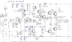
Then, after a deep breath and a brush-up on Pass, Self and Baxandall - out went all the heavy VAS collector loading components: R623 (33k2), C607 (330p) (both loads to ground) and C609 (150p), the Ccb on the output driver.
In their place, a new light 33p C609, and a two-pole Miller setup in place of C611 as shown below. Tried it both with the Miller capacitors reversed and not.
Stability tests: Completely stable with 8 Ohm // 2.2uF load. Bandwidth unchanged 3Hz - 65kHz. Tested the previous treble tone control issue - still no instability. Sweet!
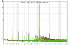
And the already improved Rotel just got better, the spectrum plot below should be read as follows:
Black trace - improved (-20dB) circuit (THD 0.0028%),
Red trace - two pole Miller Cdom mod (THD 0.0017%),
Green trace - two pole Miller Cdom reversed (THD 0.0017%).
That is a further -4dB improvement and thus almost a total of -25dB better than the original 0.03% Rotel circuit. Note that while the reversed Cdom does not change the THD value, it reduces the 3rd and 5th harmonic - almost down into the noise floor.
Calls for a celebration with a glass of vintage snake oil....
There is also a slight improvement in slew rate, but more on this later.
I also decided to leave the RIAA phono amp circuit as it is and address the loading problem directly in my B&O 3000 turntable.
So much to do and so little time!
Cheers,
Per
Hi chaps,
Sorry about the hiatus, all caused by another work deadline which also forced me to dismantle the audio measurement setups.
So all work and too little fun for too long!
Finally, after reloading Windows drivers, etc. and getting back to the good old RA-820AX mod project, I decided to follow the #53(?) suggestion from anatech:
Just for giggles and grins, "fix" the VAS stage. You can always put everything back later. Decide if the change is worthwhile (probably is).
-Chris
And so I did. First I put in the missing 10p Miller capacitor C611 - measured, but it had no effect whatsoever (as expected due to the dominant and rather brutal VAS transistor collector lag loading). -Chris
Then, after a deep breath and a brush-up on Pass, Self and Baxandall - out went all the heavy VAS collector loading components: R623 (33k2), C607 (330p) (both loads to ground) and C609 (150p), the Ccb on the output driver.
In their place, a new light 33p C609, and a two-pole Miller setup in place of C611 as shown below. Tried it both with the Miller capacitors reversed and not.
Stability tests: Completely stable with 8 Ohm // 2.2uF load. Bandwidth unchanged 3Hz - 65kHz. Tested the previous treble tone control issue - still no instability. Sweet!
And the already improved Rotel just got better, the spectrum plot below should be read as follows:
Black trace - improved (-20dB) circuit (THD 0.0028%),
Red trace - two pole Miller Cdom mod (THD 0.0017%),
Green trace - two pole Miller Cdom reversed (THD 0.0017%).
That is a further -4dB improvement and thus almost a total of -25dB better than the original 0.03% Rotel circuit. Note that while the reversed Cdom does not change the THD value, it reduces the 3rd and 5th harmonic - almost down into the noise floor.
Calls for a celebration with a glass of vintage snake oil....
There is also a slight improvement in slew rate, but more on this later.
I also decided to leave the RIAA phono amp circuit as it is and address the loading problem directly in my B&O 3000 turntable.
So much to do and so little time!
Cheers,
Per
Attachments
Hi Per,
Yes, that is rather better than I expected. You have every reason to be pleased. Now for the question ... how does it sound?
-Chris
Yes, that is rather better than I expected. You have every reason to be pleased. Now for the question ... how does it sound?
-Chris
Hi Per,
Yes, that is rather better than I expected. You have every reason to be pleased. Now for the question ... how does it sound?
-Chris
Well, (please note that I am absolutely rubbish at subjective audio journalistic superlatives or waffle descriptions) - but it is different, actually quite different from the "Rotel sound" which I by now have more or less become accustomed to. However, first impression is that everything is more "clinical", by which I mean that each instrument stands out in the sound stage image. But is it better? I need to set up a dual amp to speaker A/B listening test to give a more qualified answer.
At least when the music stops - there is dead silence, so the S/N dynamic ratio is clearly improved.
I should also try to make A/B tests between this amp and my J-P Hiraga class A.
More to do.....
Well, the listening test has been interesting. At first the modded RA-820AX sounded clearly more detailed than the stock RA-830AX which I used in the A/B comparison. But after a while, it got quite confusing - on and off it seemed to be the other way round.
So, both amps went back on the bench and fed a 10kHz square wave. The stock 830AX has a very modest slew rate of about 1 V/us (as have most Rotels from this age due to the heavy lag stability circuitry loading). The modded power amp was clearly faster - maybe to the point of being close to instability. So I guess I need to throttle the SR back to within a safe margin, and will be trying to aim for about 5 V/us which should give a full 37V swing at 20kHz.
So, both amps went back on the bench and fed a 10kHz square wave. The stock 830AX has a very modest slew rate of about 1 V/us (as have most Rotels from this age due to the heavy lag stability circuitry loading). The modded power amp was clearly faster - maybe to the point of being close to instability. So I guess I need to throttle the SR back to within a safe margin, and will be trying to aim for about 5 V/us which should give a full 37V swing at 20kHz.
Hi Per,
Why not just hit it with some differentiated square waves (having a fast rise time) and see if it rings or not? Do that with some various loads and I think you could confidently determine if it was near instability or not. Do this with the stock amp to see what is normal first. It is possible the modifications made the amp more stable, or you might have to adjust the lead compensation.
-Chris
AngelP, that's a first-rate job of applying a few basic engineering principles in just about the simplest manner possible to get a stunning result.
I wonder if the original designer is still around to see your mods and then go bang his head into a wall.
Stan Curtis was the original designer of the Rotel 820 series. He has quite a cult following:
Stan Curtis, Engineer, my clients past & present
I remember trying to improve the sound of my 820 and it was easy to make it sound a lot worse.
Looks like some of the Cyrus stuff, which gets good comments on this thread, might have been down to him as well!
Slew-induced distortion tends to set in long before you actually hit slewing limits, so it's certainly a good idea to have about a factor of 10 to spare. Then even a headphone amp can use 3 V/µs, and 1 V/µs seems way too slow for a speaker amp.
Some excellent results there (with a relatively modest amount of parts changes no less), though I wonder where the improvement in noise would be coming from, as I'd expect that to be dominated by the preamp section. The tone controls may worsen it though, so maybe they were simply turned off. Speaking of those, watch out for scratchy bass pot when throwing out C601/602.
Some excellent results there (with a relatively modest amount of parts changes no less), though I wonder where the improvement in noise would be coming from, as I'd expect that to be dominated by the preamp section. The tone controls may worsen it though, so maybe they were simply turned off. Speaking of those, watch out for scratchy bass pot when throwing out C601/602.
Oops.... firstly, my apologies to Stan Curtis, all Rotel affectionadas and a note to self:
Never try to read a slew rate from the oscilloscope trace late in the evening with tired eyes!
I re-measured both a RA-830AX and a RA-831AX mkII this morning and the stock slew rate is indeed about 10 - not 1 V/us.
The modded 820AX is still a bit faster and it is not ringing on square waves. But, I also broke my own rule to change only one thing and only in one channel - then measure, and so on. And now, after half a minute of circuit warm-up I have an irritating 38MHz / 40mVrms sine on all rails - which I need to find the root cause of. So, I need to isolate one channel, re-trace and revert my recent VAS mod steps and try again.
Oh, the joy of modding!
38 MHz? That must be something fairly local. Probably in the output stage, at least there aren't too many other things that would take half a minute to warm up. How does quiescent current behave over this time, does it go up or down?
With your change in compensation you've also changed VAS output impedance, which may be the problem here. Maybe try the other, only slightly worse-performing setup?
With your change in compensation you've also changed VAS output impedance, which may be the problem here. Maybe try the other, only slightly worse-performing setup?
Yep, it is a small, but stable 38MHz sine on top of all traces and literally measurable everywhere. The bias dc remains stable at 4mV / 18mA. I tried to turn it down to zero - without any effect on the RF sine.
I then tried to turn off the amp and power just the preamp from external +/15V supplies - all stable. Then, I powered the entire amp from a +/- 27Vdc lab supply - dc current normal at 41mA, but the 38MHz sine still appeared.
So, as you say it must be local and the most probable culprit is of course the VAS stage, as the last mod was to remove its heavy lag compensation. The 2SC1941 heats up to about 40oC within half a minute after turn on.
Not sure what you mean about scratchy bass pots when removing the input DC block capacitors C601/2 (they are already long gone in this amp). Scratchy pots are always bad, but both ends of this pot are (almost) at dc zero?
Hi Per,
Keep an open mind. Either channel could be setting this oscillation off, but the one warm output transistor looks guilty on the channel likely to do this. Make certain the heat sink is either grounded directly to the chassis, or through a capacitor, 1 nF ought to do it.
If an amplifier is going to be unstable, you would normally see ringing in the output on fast wave form edges. But at 38 MHz, it almost has to be a driver or output transistor. Sgrossklass has that exactly right.
Any control that can have a DC component across it will often be noisy - even if the control is perfectly okay. Tone controls are normally high impedance, so a good type of capacitor shouldn't cause any problems. If you can run without capacitors - great. Put coupling caps in if you do end up with some DC offsets or scratchy controls.
-Chris
Thanks to Dave S for the link to Stan Curtis' pages. They were new to me and I particularly enjoyed his "Safari" articles:
Stan Curtis, Engineer, articles from HiFi Critic magazine
Stan Curtis, Engineer, articles from HiFi Critic magazine
Thanks to Dave S for the link to Stan Curtis' pages. They were new to me and I particularly enjoyed his "Safari" articles:
Stan Curtis, Engineer, articles from HiFi Critic magazine
Yes he's a great character (maybe not the world's best business man 🙂).
In amps with no high voltages around I use the "capacitive finger test" to locate the likely source of the oscillations. It's very simple:- just place a finger on the tracks of the pcb and watch the scope, you can usually make the oscillation get worse or disappear by placing your finger in a particular location. If the "hooting" gets worse you need to consider why capacitance across the traces makes things worse and damp it somehow, if it gets better just add a few pF in the same place. I am not saying this is the ideal fix, but it shows you where to look and gives some clues as to why.
Rotel Mod Stage 5: -28dB THD reduction achieved! Can we go to -30dB??
I finally got back to the RA-820AX and undid the most recent VAS modifications. The MHz oscillation disappeared duly, never to be seen again. Bowing my head in shame, I can't rule out that it most probably may have been yours truly that had produced a late night dry solder joint somewhere on the PCB or in the airwires. Anyway, by then I had received some rare “old stock” of TL011C, TO-92 Current Mirrors (CM). This product has been discontinued by Texas for quite some time, but as it is not easy to find through-hole CM components these days, I decided to give them a go and to replace the input collector resistor R605 with the TL011C and …... it didn't work. Amp output hovering about 11Vdc, so clearly the CM didn't work properly.
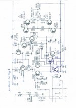
I then resorted to read the the instructions (the datasheet) and realised that TL011C is a Wilson CM with an extra transistor in the mirror path, so it needs at least 1.2V across it to turn on, and the original R605 only has about 0.9V from the VAS and its emitter resistor. So I needed another diode voltage drop in the VAS stage and replaced the 2SC1941 with a ZX603 Darlington – that didn't work either. Too much current gain?
Ok, back to the trusted old 2SC1941 which I fitted with a glued-on 2SC1845 emitter follower connected as shown in the schematic. Surely, you would think that trusted solution would finally work?.....No way, Jose. I tried one of the other TL011C samples – same result. Perhaps there is a reason why these components were discontinued? I can't explain it.
So, I decided to make my own CM modules. Done on a piece of SMD stripboard holding a NXP BCM61B and two 100E 0.1% emitter resistors, it fits nicely in the place of the R605. And, finally: YES!
I say “if ever” because I realise that I by now may have gone OTT on this project and may be boring the life out of other people with my marginal modification madness. For that I do sincerely apologize.
However, I always try to reach the goals I set myself – and I definitely don't like losing bets. But I do hear the choir asking “how does it sound?” so perhaps this is the point for the amp to finally leave the workbench and be embedded into the audio rack?
Cheers,
Per
I finally got back to the RA-820AX and undid the most recent VAS modifications. The MHz oscillation disappeared duly, never to be seen again. Bowing my head in shame, I can't rule out that it most probably may have been yours truly that had produced a late night dry solder joint somewhere on the PCB or in the airwires. Anyway, by then I had received some rare “old stock” of TL011C, TO-92 Current Mirrors (CM). This product has been discontinued by Texas for quite some time, but as it is not easy to find through-hole CM components these days, I decided to give them a go and to replace the input collector resistor R605 with the TL011C and …... it didn't work. Amp output hovering about 11Vdc, so clearly the CM didn't work properly.
I then resorted to read the the instructions (the datasheet) and realised that TL011C is a Wilson CM with an extra transistor in the mirror path, so it needs at least 1.2V across it to turn on, and the original R605 only has about 0.9V from the VAS and its emitter resistor. So I needed another diode voltage drop in the VAS stage and replaced the 2SC1941 with a ZX603 Darlington – that didn't work either. Too much current gain?
Ok, back to the trusted old 2SC1941 which I fitted with a glued-on 2SC1845 emitter follower connected as shown in the schematic. Surely, you would think that trusted solution would finally work?.....No way, Jose. I tried one of the other TL011C samples – same result. Perhaps there is a reason why these components were discontinued? I can't explain it.
So, I decided to make my own CM modules. Done on a piece of SMD stripboard holding a NXP BCM61B and two 100E 0.1% emitter resistors, it fits nicely in the place of the R605. And, finally: YES!
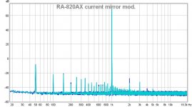
1) Amp stable, offset down to 1mV
2) Slew rate over 15 V/uS with no overshoot or ringing on a 20 kHz square wave
3) Bandwith: 3Hz to 153kHz (+0/-3dB)
4) THD now at 0.0012% - that is a massive -28dB improvement over the original spec. - or in other words the THD now down to less than 4% of the original.
The Stage 5 CM mod (light blue trace) seems to reduce the even harmonics, whereas the abandoned Mod Stage 4 (dark blue trace) T-shaped local Miller VAS feedback did its magic mainly on the odd harmonics. So, if there is ever to be a Mod Stage 6 it should probably be to combine the two.
I say “if ever” because I realise that I by now may have gone OTT on this project and may be boring the life out of other people with my marginal modification madness. For that I do sincerely apologize.
However, I always try to reach the goals I set myself – and I definitely don't like losing bets. But I do hear the choir asking “how does it sound?” so perhaps this is the point for the amp to finally leave the workbench and be embedded into the audio rack?
Cheers,
Per
Attachments
Hi Per,
Congratulations to you for pursuing the problem to its source and fixing it! You really improved this amplifier by a huge amount. I think you should definitely post further on how it sounds along with any other changes you decide to try.
When something doesn't work due to your own mistake, it is easy to throw in the towel and walk away. But going back in and trying another approach shows tenacity and determination. The educational value to yourself is far greater than what you posted, because you learned a bunch of little things along the way too. The mark of a really great technician.
So yes, I have to ask in all seriousness ... how does it sound? And the next question for you. Will you apply this change to some of your own sound equipment? In other words, is the improvement in sound quality worthwhile to perform these general changes to your own gear?
-Chris
- Home
- Amplifiers
- Solid State
- Improve a Rotel amp THD by 20dB!