Disagree completely. THD is a valid measurement and does say something about design, but it is only one of a few measurements made. The residual from a good THD meter has a wealth of information to uncover in it.
Bad analogy, but I'll try it anyhow. Your blood pressure doesn't say much about how healthy you are by itself, but it is still a valuable indicator when taken with other information. Just because we don't understand the information doesn't mean a doctor should ignore it. In the same way, THD can give you some idea of build and design quality in general terms. Similar to what blood pressure can tell you. IM distortion is similar to THD in what it can tell you. It's the other detailed info that we don't get that says more. Most of us wouldn't understand it though.
Pushing down distortion is a worthwhile pursuit, because we normally fix other issues while doing that. Even the stuff we aren't measuring for. In truth, big changes in sound quality are often accompanied by a small THD figure change. We can measure the improvement, it's just that the change in numbers isn't as large as the subjective change.
-Chris
Last edited:
As per your suggestion, I reverted to the L_in – L_tape out and tried all sorts of grounding and shielding of the input circuitry to reduce the 50Hz noise – no luck. I finally found that the culprits were indeed the 1K tape out series resistors. Firstly, they were physically placed only a few mm away from one of the IC power supply input ripple capacitors (Fig 1) – although relocating them to a more “quiet” part of the PCB did actually not improve things that much.
However, simply shorting them did (Fig 2), also note that the strange green 2kHz peak is gone. Apparently, the 1K's were picking up the eddy currents from the transformer to the 820AX's casing as the 50Hz peak actually dropped when I removed the top cover. Now, due to the design of the 820AX there are no easy ways to break or isolate these eddy loops – nor can you easily rotate or move the mains transformer.
So, unless someone comes up with a great new idea, I guess that we are stuck with what we got.
[/COLOR][/QUOTE]
An old idea from the days of EI transformers was to use brass spacers and brass machine screws to mount these inside a steel chassis to deal with eddy currents. You might be able to find some way to emulate this with a toroid.
Ok, I have now tried just about every practical trick up my sleeve to further reduce the 50Hz peak in the RA-820AX, and all now seems as tinkering around the box with little effect:
I have pulled out the original bridge rectifier, put another in far away from the circuits, measured -
applied differing snubber networks according to the relevant threads on this blog, measured -
took this bridge completely out of the box, measured -
put in a dual inductor choke before the reservoir caps, measured -
isolated the ground star point to chassis contact, measured -
put in a 250ohm between these two - measured.
It appears that there are mainly four peaks in the spectrum that have stubbornly remained more or less unchanged by every mod, namely the 50Hz, the 150Hz (unless you supply the power at DC from outside of the box), and since mod 1: the 2 and 3kHz harmonics.
For the first two peaks – well, I didn't design a custom transformer/bridge shielding box-in-boxes - as I decided that was a mod too far. The 2nd/3rd harmonics are probably a function of the Rotel's power stage audio path topology, which I also (still) haven't changed.
But, if we recap, what has been achieved?
And last but not least – having good fun achieving these targets (and winning some bragging rights). Further, sorting out the less-than-optimal RTA setup and gaining further insights.
On that note, here is a little fun challenge for y'all:
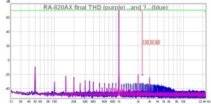
The final THD spectrum for the 820AX is the purple trace on the attached pic.
Using the exact same circuit and same RTA settings, occasionally I got the more noisy blue track response.
- What do you think could have caused this?
No first prize – and second prize is double that.
Cheers,
Per
I have pulled out the original bridge rectifier, put another in far away from the circuits, measured -
applied differing snubber networks according to the relevant threads on this blog, measured -
took this bridge completely out of the box, measured -
put in a dual inductor choke before the reservoir caps, measured -
isolated the ground star point to chassis contact, measured -
put in a 250ohm between these two - measured.
It appears that there are mainly four peaks in the spectrum that have stubbornly remained more or less unchanged by every mod, namely the 50Hz, the 150Hz (unless you supply the power at DC from outside of the box), and since mod 1: the 2 and 3kHz harmonics.
For the first two peaks – well, I didn't design a custom transformer/bridge shielding box-in-boxes - as I decided that was a mod too far. The 2nd/3rd harmonics are probably a function of the Rotel's power stage audio path topology, which I also (still) haven't changed.
But, if we recap, what has been achieved?
- A total removal of audible 100Hz hum.
- A dramatic ten fold reduction in THD from 0.03% to 0.003%.
- Removal of the output DC offset.
- All electrolytics in the audio path either removed or replaced with film capacitors.
- Transforming a “speaker killer” into a “speaker thriller”
And last but not least – having good fun achieving these targets (and winning some bragging rights). Further, sorting out the less-than-optimal RTA setup and gaining further insights.
On that note, here is a little fun challenge for y'all:
The final THD spectrum for the 820AX is the purple trace on the attached pic.
Using the exact same circuit and same RTA settings, occasionally I got the more noisy blue track response.
- What do you think could have caused this?
No first prize – and second prize is double that.
Cheers,
Per
Attachments
Hi AngelP,
Excellent work to a reasonable level. You kept the improvements within a decent budget and got the biggest bang for the money as well.
Your extra harmonics and noise could easily be a different ground point for a probe. You are -90 dB for the extra hash, so it isn't going to be a massive problem. I am interested in what you found as the cause.
-Chris
What about injecting a tiny amount of antiphase hum to null out your spike?
The JLH technique 😉
The JLH technique 😉
Interesting suggestion. I haven't read anything by JLH on this subject, any links?
I did use something like it on one of my very first restoration projects, an old Rotel RA-412, where I could not for the life of me understand why someone had put in two different reservoir caps - different makes, values and sizes.
But, as Mooly put it: It is like that for a reason.
Which I found out after putting two identical new spunky caps in place - I had just let the hummingbird out of the cage. Purely by chance, after spending quite some time poking around trying to break or short any hum loops - that a "gentle" poke (equal to a 0.33 ohm contact resistance) in certain ground places suddenly cancelled the hum. A big 5W wirewound paralleled over the ground copper track leading to the preamp, soldered two inches apart did the trick, although I felt a bit like having ventured into Voodoo land.
The next repair guy will probably look at this and think "What looney put that there, it is not in the diagram and it is totally shorted by the track!?" and rip it out.
Well I guess that hummingbirds have a right to life too. 😉
Interesting suggestion. I haven't read anything by JLH on this subject, any links?
It was just a comment he made in a series of articles 'JLH a lifetime in electronics' that ran in the March to June 2000 Electronics World mags. A fascinating insight and a really good read. I remember thinking at the time, what a brilliant idea !
Attachments
Hi AngelP,
Excellent work to a reasonable level. You kept the improvements within a decent budget and got the biggest bang for the money as well.
Your extra harmonics and noise could easily be a different ground point for a probe. You are -90 dB for the extra hash, so it isn't going to be a massive problem. I am interested in what you found as the cause.
-Chris
Ok, I guess that I might as well just reveal the noise culprit:
The blue noise signal on the enclosed RTA trace is what you get if you turn on an energy saving (CFL) lamp placed at a 45deg angle and a 1m distance from the amp circuits (amp top cover off).
This made me think a): Will the increased amount of "green" energy saving lamps and their increased total broad spectrum electrical noise which we are now surrounding ourselves with actually turn us - green?
Or b): does this merely show the impressive sensitivity of a modern RTA measurement setup?
Anyway, I can follow the comments sgrossklass put forward that a low THD is not the holy grail of good amp performance, but as Chris pointed out - the opposite is probably true. If you have a serious THD issue, you can be certain that there is a problem somewhere and other amp quality parameters are probably shot too.
I use the RTA all the time, either when tapping components or using freezer spray. If there is a dodgy solder joint or a failing component you get a clear visual response. Sometimes I even have it (and the amp) turned on while trying different mods or compensations - but then again I am a very brave person with a (mostly) steady probe hand. But also with a few bright flash bang memories!

Attachments

Ok, I guess that I might as well just reveal the noise culprit:
The blue noise signal on the enclosed RTA trace is what you get if you turn on an energy saving (CFL) lamp placed at a 45deg angle and a 1m distance from the amp circuits (amp top cover off).
This made me think a): Will the increased amount of "green" energy saving lamps and their increased total broad spectrum electrical noise which we are now surrounding ourselves with actually turn us - green?
Or b): does this merely show the impressive sensitivity of a modern RTA measurement setup?
Anyway, I can follow the comments sgrossklass put forward that a low THD is not the holy grail of good amp performance, but as Chris pointed out - the opposite is probably true. If you have a serious THD issue, you can be certain that there is a problem somewhere and other amp quality parameters are probably shot too.
I use the RTA all the time, either when tapping components or using freezer spray. If there is a dodgy solder joint or a failing component you get a clear visual response. Sometimes I even have it (and the amp) turned on while trying different mods or compensations - but then again I am a very brave person with a (mostly) steady probe hand. But also with a few bright flash bang memories!
Perhaps you might try your CFL lamp testing with another subject amplifier. It would be interesting to see if the same result is obtained or whether the finding is specific to your Rotel.
Perhaps you might try your CFL lamp testing with another subject amplifier. It would be interesting to see if the same result is obtained or whether the finding is specific to your Rotel.
mjona, I'm afraid that the CFL has already gone to recycling heaven (or the other place).
I should mention that it was pretty blackened and the socket discoloured, so it could well have been on its last legs. I replaced it first with a halogen and then with a LED, neither of these gave any problems on the RTA trace.
Hi AngelP,
I know how you feel about the source of your noise. My old PM3070 oscilloscope made aligning FM tuners impossible (or nearly so). It took me a while to find the source - guess what I was using to verify interference in the IF stage? Yup.
A new (to me) replacement oscilloscope was the way out. I bought the PM3070 brand new, so I was very put out that it had that problem. The scope had one of the better traces compared to all the big names. That scope? Gave it to my brother in law. He's happy with it.
-Chris
Last edited:
This is getting a bit scary! My trusted old favourite storage scope - a PM3375 (which I also bought from new) could possibly have read along or hacked this blog - because it suddenly decided to stop working. When turned on, it now just gives a sorry whine from the smps and that's it.
Except for a very faint message on the CRT display which I swear reads: DO NOT GIVE ME AWAY - REPAIR ME, PLEASE!!!
IoT is here already........
-Per
Except for a very faint message on the CRT display which I swear reads: DO NOT GIVE ME AWAY - REPAIR ME, PLEASE!!!
IoT is here already........
-Per
Hi AngelP,
Mine did the same thing, and I fixed another that died as well. In the PM3070, the power supply PCB runs down the side where the power switch is. All this should take is a set of new capacitors. Most are axial lead, so use the same type. A couple are tight in size, but I tried to up the voltage rating as they were replaced. I bought all my capacitors from Digikey and used the best types (higher temp ratings and highest voltage rating for the size with also the best ripple current ratings). In a few spots I was forced to use the Philips brand, but basically got the best types in that line that would fit. I would replace them all to avoid having to go in there again later on.
-Chris
Ok, finally sorted out the full treble control setting oscillation problem. Turned out that the power amp was ok, but the OPA2134 did not like the redesigned tone control and/or dc loading. Oscillation at treble pot max was somewhere in the MHz region.
So, as a first step I replaced the old pre-amp 100uF DC stabilization E-lytes with 10uF Tantals and hey presto, I could no longer force the amp into oscillation.
To be on the safe side (and because the PCB holes were so conveniently there), I put a 10ohm/100pF pole circuit inside the feedback loop from the output to the non-inverting input - which normally hugely increases a FET opamp's tolerance of difficult loads.
Having a few pounds to spare from the original GBP 40 budget, I decided to do a couple of extra modifications. First, for my vinyl addiction, I replaced the venerable NE5532 opamp in the Phono stage with another OPA2134, Silmic capacitors in the feedback and replaced the electrolytics at the output of the stage with Wima film capacitors. Not because the now improved low-offset stage needs them, but mainly to establish a 5Hz highpass “Rumble” filter – as there is no need to amplify the movement of the pickup from any vinyl record warp or center hole offset – should such abberations ever come across my turntable.
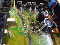
Then I put the two 10ohm/100nF output Zobel networks back in their places on the PCB – I don't know why Rotel left out this completely sensible and inexpensive inductive load instability protection (Mind you, it may possibly have cost them in complaints and claims, as Zobels were promptly designed back in again in the RA-900 series.) Picture 1 shows the very discreetly modded PCB. It takes a trained eye to spot the modifications, but note the super-glued TO-92 input and input current stage cascode pairs.
Lastly, I inserted a speaker delay/protection relay board – mainly to stop the irritating turn-on “thump” which I admit had got more loud and sharp after the modifications.
I understand that some of these measures may be against the “Rotel philosophy”, but going back to where all this started – the 4A speaker fuses did absolutely nothing to protect the poor frying woofer coils from the standing +16Vdc on the speaker terminals – did they now?
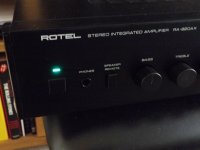
Cosmetically, I replaced the rather cheap looking red power LED with a custom made emerald green one - in keep with the old Rotel lamp colour tradition, it now looks as great as it sounds.
And sound great it does....
So, as a first step I replaced the old pre-amp 100uF DC stabilization E-lytes with 10uF Tantals and hey presto, I could no longer force the amp into oscillation.
To be on the safe side (and because the PCB holes were so conveniently there), I put a 10ohm/100pF pole circuit inside the feedback loop from the output to the non-inverting input - which normally hugely increases a FET opamp's tolerance of difficult loads.
Having a few pounds to spare from the original GBP 40 budget, I decided to do a couple of extra modifications. First, for my vinyl addiction, I replaced the venerable NE5532 opamp in the Phono stage with another OPA2134, Silmic capacitors in the feedback and replaced the electrolytics at the output of the stage with Wima film capacitors. Not because the now improved low-offset stage needs them, but mainly to establish a 5Hz highpass “Rumble” filter – as there is no need to amplify the movement of the pickup from any vinyl record warp or center hole offset – should such abberations ever come across my turntable.
Then I put the two 10ohm/100nF output Zobel networks back in their places on the PCB – I don't know why Rotel left out this completely sensible and inexpensive inductive load instability protection (Mind you, it may possibly have cost them in complaints and claims, as Zobels were promptly designed back in again in the RA-900 series.) Picture 1 shows the very discreetly modded PCB. It takes a trained eye to spot the modifications, but note the super-glued TO-92 input and input current stage cascode pairs.
Lastly, I inserted a speaker delay/protection relay board – mainly to stop the irritating turn-on “thump” which I admit had got more loud and sharp after the modifications.
I understand that some of these measures may be against the “Rotel philosophy”, but going back to where all this started – the 4A speaker fuses did absolutely nothing to protect the poor frying woofer coils from the standing +16Vdc on the speaker terminals – did they now?
Cosmetically, I replaced the rather cheap looking red power LED with a custom made emerald green one - in keep with the old Rotel lamp colour tradition, it now looks as great as it sounds.
And sound great it does....
Attachments
NE5532 to OPA2134 in an MM phono stage? That's a sidegrade at best, with somewhat worse noise levels. (Note that due to RIAA EQ, output noise predominantly originates from mid/low frequencies despite the rising source impedance, so ultimately low voltage noise is of more use and low current noise of less use than one may think.) HF THD may turn out marginally higher as well due to input impedance distortion (and somewhat lower GBW), though still far below vinyl/cartridge levels. NE553x have everything it takes for a good phono stage opamp, and beatiing them is not entirely trivial. LM833 and NJM2068 are lower in noise but fare worse for output driving abilities, for example.
Back in those days, a '5532 would have been a premium part. If it's a Philips/Signetics one, you are well-advised to keep it, these have been discontinued for more than a decade now and do a fair bit better in terms of common-mode distortion compared to a lowly TI job (i.e. should give less distortion in low-gain inverting circuits). Obviously an LM4562 will generally do better nowadays, but those have only been available for like 7 years.
Back in those days, a '5532 would have been a premium part. If it's a Philips/Signetics one, you are well-advised to keep it, these have been discontinued for more than a decade now and do a fair bit better in terms of common-mode distortion compared to a lowly TI job (i.e. should give less distortion in low-gain inverting circuits). Obviously an LM4562 will generally do better nowadays, but those have only been available for like 7 years.
NE5532 to OPA2134 in an MM phono stage? That's a sidegrade at best, with somewhat worse noise levels. (Note that due to RIAA EQ, output noise predominantly originates from mid/low frequencies despite the rising source impedance, so ultimately low voltage noise is of more use and low current noise of less use than one may think.) HF THD may turn out marginally higher as well due to input impedance distortion (and somewhat lower GBW), though still far below vinyl/cartridge levels. NE553x have everything it takes for a good phono stage opamp, and beatiing them is not entirely trivial. LM833 and NJM2068 are lower in noise but fare worse for output driving abilities, for example.
Back in those days, a '5532 would have been a premium part. If it's a Philips/Signetics one, you are well-advised to keep it, these have been discontinued for more than a decade now and do a fair bit better in terms of common-mode distortion compared to a lowly TI job (i.e. should give less distortion in low-gain inverting circuits). Obviously an LM4562 will generally do better nowadays, but those have only been available for like 7 years.
Very interesting points. Well, I put in a good quality turned pin IC socket so I guess there's a chance to try to measure the differences. I think I may have most of the amps you mention in stock, including Signetics and TI versions of 5532. And, I believe, a couple of LME49720HA - any views on that?
However, it will not be anytime soon, as I have been ordered on holiday for the next couple of weeks by The Supreme Command. 😎
NE5532 to OPA2134 in an MM phono stage? That's a sidegrade at best, with somewhat worse noise levels. (Note that due to RIAA EQ, output noise predominantly originates from mid/low frequencies despite the rising source impedance, so ultimately low voltage noise is of more use and low current noise of less use than one may think.) HF THD may turn out marginally higher as well due to input impedance distortion (and somewhat lower GBW), though still far below vinyl/cartridge levels. NE553x have everything it takes for a good phono stage opamp, and beatiing them is not entirely trivial. LM833 and NJM2068 are lower in noise but fare worse for output driving abilities, for example.
Back in those days, a '5532 would have been a premium part. If it's a Philips/Signetics one, you are well-advised to keep it, these have been discontinued for more than a decade now and do a fair bit better in terms of common-mode distortion compared to a lowly TI job (i.e. should give less distortion in low-gain inverting circuits). Obviously an LM4562 will generally do better nowadays, but those have only been available for like 7 years.
Hi.
Back from holidays directly into to a couple of disasters at work - but then again, what's new?
Anyway, also back to the phono preamp comments above. My RIAA spec knowledge is a bit rusty so please correct me if I make a complete dodo of myself.
First, let me explain why I chose to replace the venerable NE5532 with OPA2134. The Rotel RIAA preamp circuits are direct DC coupled to the MM cartridge (i.e. no input electrolytic cap). As I remember, a MM cartridge can be generically modelled as a small inductor in series with a 1.5kohm resistor which is why it is recommended to load it with at least 47kohm. So if the opamp has any significant input currents it will mainly run through the cartridge, and the 5532 NPN input can pull up to 0.8uAdc input bias current – doesn't sound as much perhaps, but plenty for a small inductive generator and definitely not conveying for lowering the dominant vinyl/cartridge distortion. Put another way, the input resistance of the 5532 can be as low as 30kohm, effectively loading the cartridge with about 18kohm.
Which I guess is why many other quality amps of the time had a discrete JFET pair up front in the preamp input circuitry. The matched OPA2134 integrated input JFET pair outperforms such discrete solutions by a good margin, input currents are in the low pA region and input impedance is practically infinite for audio use. Voltage noise figures are comparable with the 5532, all other specs are better.
Please note that I am definitely not trying to put down the trusted old NE5532, but as impressive it was when it was launched, so are the improvements that Burr-Brown and other analogue amp designers have come up with in recent years.
But, as I said, we got the opportunity to do some measurements to check it out.
Cheers,
Per
Attachments

Hi Per,
Sounds like a plan.
At some point you should figure out what the total capacitance that the cartridge sees, including your phone preamp. Subtract that from the recommended capacitance and pad up or down as required. This simple step will often make the biggest change in sound quality once you are playing at the levels that you are.
I'm interested in what you find here.
-Chris
- Home
- Amplifiers
- Solid State
- Improve a Rotel amp THD by 20dB!