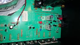
Hello, happy new year all! Got my hands on a RB-981 amp, AngelP I was wondering about two caps in particular, the 22uf 63V one and 220uf 63V one C803 and C804 respectively, I have some, they are Capixon, or something like that, upon cleaning they leak some black stuff from underneath, I have some 470uf 63v and 100uf 63v Panasonic FC lying around, would the work in this position? I think it's some filtering for the bridge circuit? or protection circuit?
Thank you
Thank you
Hi Criss,
Yes, they sit in the protection circuit's DC supply, and it sounds like they may have been replaced on the cheap at some point.
The tech manual indicates 100V capacitors, but I guess that 63V types will do - if the rails are still 56V (of course dependent on the actual mains voltage in your area).
Also, the Panasonics seem to actually be tested and able to withstand their claimed voltage over time, whereas some cheapo caps clearly can't.
Upping the values is probably ok as well - if the caps fit on the pcb, but personally I would get some direct replacement 22 and 220uF 100V Panasonics.
Why do all the work and then put in some compromise stuff to save a few pennies?
Thanks, well I also have 220uf 100V and 22uf 100V Elna Silmic II, should I pop them in? Also for the DC coupling caps, 4.7uf original Black Gate, I have three options: 4.7uf Wima MKS2, 10uf X7R Ceramic from Murata, and 10uf Tantalum 50V, as per your experience, which should I put in this position? I'm thinking I should go with the MKS2, but I heard Ceramic or Tantalum might be better here?
Thanks for your time and help
Thanks for your time and help
Silmics are fine.
As for the input capacitor, I would never put a ceramic or tantalum cap in the audio signal path, they are not designed for that.
I use the Wima MKS2 Polyethylene-terephthalate (PET) film caps.
Yes, yes I know...... there are many people who thumb their noses at PE-type caps and swear by bigger and more expensive PS or other film types.
And I know that these have got better HF specs, but frankly I haven't been able to hear any difference in any of the blind tests I have participated in.
I like the Wimas because of their high quality and solid build so that they can sit firmly on the pcb without any vibration, most often fitting nicely in place of the caps they replace.
I totally agree on the MKS2 types, I did some time ago some comparisons in my RA-971 MKII with mks2 vs MKP4/10 vs Visaton MKP, and some Jantzen MKP (blue ones) could not hear any difference with my Topping D50s DAC connected directly in the CD in of the Rotel, I'll stick some 4.7uf MKS2's in there like I usually do then 🙂
One last question if I may, upon inspecting the schematic, it seems there is space on the power button board for an additional cap, (c0002) it seemes to be line to line cap? should I stick a X2 Wima in there? I have a box of them, if yes what value should I go with? maybe 0.047uf?
Thanks AngelP for your time 🙂
I would leave that space empty, I don't remember any Rotel that have such an X2 cap across the mains.
Hello AngelP, ubon having time to analise the schematic, I found a rather odd thing, the 680pf capacitor that shunts to ground on the input, I thinks it's forming a low pass, but with 33kohm impedance will it not start to cutoff at about 7kHz? why this value? should I lower it to say 470pf? maybe even 220pf?
Thank you for your time and help
Criss
Thank you for your time and help
Criss
No, the 680pF forms a LP filter with R605/6 470E which gives 500kHz. The 33k forms a HP filter with the 4.7uF - ie. 1 Hz.
So all is ok.
So all is ok.
Thanks for the clarification, original is 680pf Wima FKS2, I have some modern FKP2 but 470pf, should I swap?
Only if your hearing range is up to 350-500kHz. 😊
😊
I know, I know... it is so easy to get carried away when doing these upgrades, but part of the art is to also show restraint.
If a circuit is working as intended (and far away from the audio spectrum) - leave it alone to do its job.
😊 I know, I know... it is so easy to get carried away when doing these upgrades, but part of the art is to also show restraint.
If a circuit is working as intended (and far away from the audio spectrum) - leave it alone to do its job.

Thanks AngelP, well I upgraded only caps, and the pre-drivers, cleaned the amp, and it's all nice and dandy, I was wondering a thing, will upgrading D601-608 [1n4148], I think they are in the VAS stage for balancing and basing the vas transistors? with FDH333 diodes, be a good change? in theory they have lower noise and are faster, I have a stock of them, what's your opinion?
Thank you
Criss
Thank you
Criss
Attachments
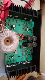
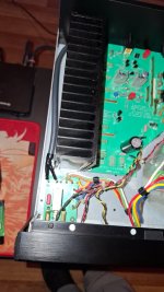
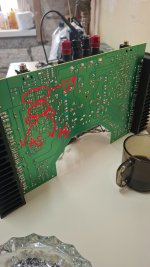
As always, thank you for your insights, helps a lot in learning, I was inclined to think they where inadequate cause I have some heat marks on the pcb on that part, don't know the cause, and it's kinda odd, I,m the 2nd owner of the amp, and it was never driven to max, only normal room listening levels, what could be the problem here? it's more pronounced on the right channel than on the left, is it of concern and can the pcb color maybe be restored?
Thank you
Criss
Thank you
Criss
Attachments
You could check the voltage across the 220E emitter resistors R619/20 and R611/12 to calculate the LTP currents, it should be around 2.7mA.
Likewise, measure across 100E emitter resistor R623/4 to get the VAS current - around 14mA.
The current through the diodes will only produce about 1mW in each, you can safely try touching them while the amp is running to check their temps.
Then, perhaps lightly(!) touch the VASs to find out what most probably has caused the darkening of the pcb.
If you are concerned you can reduce the VAS current to under 10mA by replacing all four VAS 100 ohms with say, ~150E MF.
(BTW, these DC currents run constantly - independent of amp volume or (ab)use.)
Last edited:
Hi Ange,
I went through your proposed modification but on a RA 840 BX 4.
I kept one channel unmodified to compare results.
Here are my findings: THD -11db compared to original channel , ie -81db versus specification and measure at -70 db…
Funny I compare it to my NAD 326 BEE … !
I had to leave the 1,8k resistors R625/627 or 626/628… to keep the full voltage swing , ie no clipping up to at least 57 watts 😊.
Same with R685 , shorting it reduced the THD advantage to only 3-4 db difference.
The 82 R is a super way to get no more overheating with those parts 😉.
Here is the link to the video with my small spectrum analyser 😊
Thanks for all those posts !
Eric
Hi Eric,
I only just saw your post and video, congrats with the nice result!👍
Getting beyond 11dB THD reduction does involve quite some extra tasks - matched LTPs, EF-VAS designs etc. You got most of the way with the least effort.
Now, I did see a reduction in output swing and thus lower max power when I changed the pre-VAS stage emitter resistors, but getting the VAS current down was a clear must for survival in the RA-820 BX3s as the pcb was starting to go black and the TO220 VASs wobbling in their solder joints.
Further IMHO, avoiding any reduction in power output is way down on my priority list when upgrading and something I will readily sacrifice for better sound and lower distortion performance at normal listening levels.
Ok, it may not look great on the marketing spec list, but how many people employs 57W in a domestic setting - except perhaps when staging an all night rave party🕺?
On my Angelhorns speakers I rarely go over 1-2W before the pictures fall off the wall, the cat start losing fur and the neighbours move out.😊
Anyway Eric, great work!
Per
Hi Per,
I have to agree strongly with you. Maximum power output isn't nearly as great a concern for home product as reliability and performance is concerned. I have to say I have never been in a situation where I had to make that trade-off, but I would choose as you did.
If you're using close to the max rated power, you are probably already clipping. A few watts doesn't make any difference.
Key word here is horns. With mine I'm probably not using event that much. But B&W owners and similar for sure need much more juice.On my Angelhorns speakers I rarely go over 1-2W before the pictures fall off the wall, the cat start losing fur and the neighbours move out.😊
Hi Per,
Thanks for the nice reply, I am in a different position although my cat would not stand a minute in the studio if it’s too loud, the dog gets along 😅, even with my drumming 😂😂!
I confirm the problems with the overheating and the PCB…
My repair showed me that , after I had changed the burned 1k resistors, I had to search trough the whole preamp section to find some cold solder joint or better said cracked joint/traces on the 5532 common to both channel IC702….it looked at first like switch problems , it wasn’t it was lost solder / intermittent contacts directly on the pads…(I’ll soon release the video on the repair part)
Also when I changed resistors as per your schematic , some pads had a tendency to get off from the pcb (with little heat, I was careful)……indicating high sensitivity / aging of some of the finer traces of the pcb….
When nothing makes senses, that is where too look for, when repairing this unit 😉
Thanks again for YOUR great work !
Best,
Eric
- Home
- Amplifiers
- Solid State
- Improve a Rotel amp THD by 20dB!