If this is full power 10kHz sticking then the result is absolutely acceptable. You may not have really a chance to better this behavior. Compare your results with measurements in this thread (picture 3: full power 20kHz overload):
http://www.diyaudio.com/forums/soli...s-ab-power-amp-200w8r-400w4r-post3776534.html
A VAS diode is mostly needed if you change your VAS to an enhanced VAS.
BR, Toni
http://www.diyaudio.com/forums/soli...s-ab-power-amp-200w8r-400w4r-post3776534.html
A VAS diode is mostly needed if you change your VAS to an enhanced VAS.
BR, Toni
Remove short between Q6 base and colector and replace it with 1N4148 diode (cathode to Q6 base). Than connect two antiparalell connected 1N4148 diodes between colectors Q3, Q4 (Q5, Q6). in this schematics . Without input signal here should be the same voltages (+- 50mV), so diodes will be closed. With added diodes You can omit Q12. It should improve sticking a lot.
Last edited:
There is something rotten in, where was that againRemove short between Q6 base and colector and replace it with 1N4148 diode (cathode to Q6 base). Than connect two antiparalell connected 1N4148 diodes between colectors Q3, Q4 (Q5, Q6). in this schematics . Without input signal here should be the same voltages (+- 50mV), so diodes will be closed. With added diodes You can omit Q12. It should improve sticking a lot.


Mona
Attachments
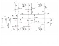
connect two antiparalell connected 1N4148 diodes between colectors Q3, Q4
OK, i will try this when i get a chance, thanks.
no, that did not work, i also added diodes for Q9 in various combinations.
although the clipping trace did alter, when pushed harder it looked worse..
overall the best clipping is still with the basic circuit (no diodes)
although the clipping trace did alter, when pushed harder it looked worse..
overall the best clipping is still with the basic circuit (no diodes)
Not sure how universally applicable this is, but I found a cure that seems to work for me. The value of the emitter resistor on the Vas stage is usually some low value like 10 or 22 ohms. That would be R11 in the circuit a couple posts above. Temporarily replace it with a 100 ohm or so trimpot. Adjust that and you may be able to better tune the clamp circuit for nice clipping and no oscillation. Then install a fixed resistor. My low power amp needed about 75 ohms and now exhibits almost perfect behavior. As usual, YMMV.
Ah, nothing's perfect. The fix does increase the high frequency THD from 0.003 to 0.015, which is unacceptable. The fix for the fix seems to be a bypass cap across the resistor, a couple uF or so. Band-Aids on top of Band-Aids make me nervous, so more testing is underway.
no, that did not work, i also added diodes for Q9 in various combinations.
although the clipping trace did alter, when pushed harder it looked worse..
overall the best clipping is still with the basic circuit (no diodes)
I agree with astx about latch up - it is hardly noticeable.
You still have a couple of diodes in the circuit in D5 and D6. These are needed in a BJT output stage which is more at risk of damage from currents generated by reactive loads and a fast switch is needed to act as a reverse bypass.
I have not seen reverse diodes in MOSFET circuits - the devices are fast enough switches in their own right that the currents generated do not build up with nowhere to go that the devices cannot withstand for a very brief duration
It is conceivable that D5 and D6 pass a small amount of current in your circuit - largely but possibly not entirely swamped out by the amounts passed by the MOSFETs.
In that case D5 and D6 are connected to the feedback loop and any switching action of these however minor will be seen as an error signal.
I suggest you delete them.
It seems basic is best. I can adjust the resistance for a nice smooth clipping waveform and high stability, but at the expense of THD. If there's a way to get both with these simple circuits, I've not discovered it.
It seems basic is best. I can adjust the resistance for a nice smooth clipping waveform and high stability, but at the expense of THD. If there's a way to get both with these simple circuits, I've not discovered it.
If you are talking the 22R Vas emitter resistor you could try a small value lead capacitor in parallel. I have seen that strategy applied in a couple of instances.
Yes, tried that but there doesn't seem to be a good compromise that keeps THD low (big cap does that) and good lower rail clipping quality (small cap does that). I've no doubt it could work well with some amps, just not the particular one I'm working on. Maybe my desires are too much- clipping on the lower rail that looks just like the textbook perfect clipping in the upper rail.
Yes, tried that but there doesn't seem to be a good compromise that keeps THD low (big cap does that) and good lower rail clipping quality (small cap does that). I've no doubt it could work well with some amps, just not the particular one I'm working on. Maybe my desires are too much- clipping on the lower rail that looks just like the textbook perfect clipping in the upper rail.
Can you post a link for this amplifier.
An observation I would make about the subject circuit is the constant current via Q8 is about 11 m.A.
The purpose of Q12 is to limit the current passed by Q9 which arises when the voltage across R11 (22R) reaches around 0.53 volts equivalent to 24 m.A.
If R11 was increased to 39R that would reduce to14 m.A.
A small lead capacitor in parallel with R11 would delay the onset of protection.
The 2SC3423 is an obsolete device however it has not failed under the test conditions. How reliable it might be with supply rails of +/- 48 volts with a current draw of 11 mA is not clear from the datasheet - there is a caution about reduced reliability if the device is allowed to run hot.
There is a question whether or not the protection circuit is going to be called into action with R11 at 22R.
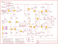
That's an interesting point. My Vas is only running about 6 mA, so how does the 10 ohm resistor ever come up with enough drop to turn on the protection transistor? It certainly does work, so the only thing I can think of is the Vas emitter follower gets turned on and the current actually flows through the bases. Seems like a lotta current for bases! Anyway, it's presently as good as I can get it. The circuit is right out of Self, with just a few minor changes. Cdom is higher than I'd like- 100 pF is sufficient, but gives me junk at the negative clip point. 270 pF seems to cure that. Though this is an audio amp, admittedly of very low power, it's used down to DC. The various grounds are labeled HCG and LCG and were brought out separately for experimentation. Various voltage drops are given so you can see the currents. Could still be a few errors between the paper and the actual circuit on the bench. I wonder if more current through the Vas would be a good idea?
Attachments
Last edited:
That's an interesting point. My Vas is only running about 6 mA, so how does the 10 ohm resistor ever come up with enough drop to turn on the protection transistor? It certainly does work, so the only thing I can think of is the Vas emitter follower gets turned on and the current actually flows through the bases. Seems like a lotta current for bases! Anyway, it's presently as good as I can get it. The circuit is right out of Self, with just a few minor changes. Cdom is higher than I'd like- 100 pF is sufficient, but gives me junk at the negative clip point. 270 pF seems to cure that. Though this is an audio amp, admittedly of very low power, it's used down to DC. The various grounds are labeled HCG and LCG and were brought out separately for experimentation. Various voltage drops are given so you can see the currents. Could still be a few errors between the paper and the actual circuit on the bench. I wonder if more current through the Vas would be a good idea?
I have sent you a P/M to avoid taking the thread in another direction.
Ah, nothing's perfect. The fix does increase the high frequency THD from 0.003 to 0.015, which is unacceptable. The fix for the fix seems to be a bypass cap across the resistor, a couple uF or so. Band-Aids on top of Band-Aids make me nervous, so more testing is underway.
The VAS emitter resistor decreases the VAS gain, and hence the loop gain, and the result is more distortion.
OTOH, lowering the open loop gain (to start with) is good for controlling the clipping behavior. The Baker clamp effect is essentially killing (unfortunately in a poorly controlled way) the VAS gain when an overload condition occurs. If you start with a high open loop gain, since the feedback loop is still closed, lowering the overall open loop gain may lead to a feedback loop instability (with the known ugly artifacts). That's why an optimally implemented clipping protection needs frequency compensation, unfortunately impossible to implement in the basic Baker clamp (which is pretty much a brute force method).
I believe the clipping behaviour (with the associated potential instabilities) is one of the root causes for most of commercial amps avoiding two pole compensation (think how two pole compensated amps are usually only conditionally stable, meaning at lower closed loop gains they can easily oscillate), and also behind the myth of "low feedback" magic sonic qualities. Lacking a proper clipping/overload protection that would kill a high open loop gain in a controlled manner, so that stability is always maintained (which is by no means simple to design), low feedback and/or simple Miller compensation are simply yet another suboptimal performance vs. stability trade.
Just a point in defence of the clamp not that I am an advocate - the Vas emitter needs to source more current from the negative rail than the CCS can sink to the positive rail - in order to drive the output stage.
The extra amount would depend on the current gain of the output stage and the speaker load - with some allowance for this being driven out of phase.
This and the power should latter should be part of the specification.
Then the value of the emitter resistor selected so the clamp is not activated during normal use. It should be able to limit under fault conditions.
This does require more thinking than fitting stopper resistors in the feed to the driver bases.
The two pole comp did make me nervous, but I did a large amount of testing with single and double pole and am pretty convinced it isn't affecting the clipping performance. Getting a better handle on how the clamp works, I started to wonder about base ratings of small signal transistors. None of the data sheets I've looked at specify a max Ib, which seems strange. Any insights? I did raise R98 to 20 ohms.
Right now the clipping performance is good and I'll post some photos when I get the chance. This was a nice circuit for higher impedance loads, like headphones, producing < .001% THD over the entire audio band, but in trying to drag more current out of it, there are many things I'd refine!
Right now the clipping performance is good and I'll post some photos when I get the chance. This was a nice circuit for higher impedance loads, like headphones, producing < .001% THD over the entire audio band, but in trying to drag more current out of it, there are many things I'd refine!
- Status
- Not open for further replies.
- Home
- Amplifiers
- Solid State
- implimenting a baker clamp