clipping latch-up solutions?
hi,
this amp has a bit of latchup when pushed into clipping (same results with no load and into 7ohms).
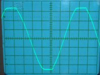
I put two 1n4148 diodes in series with Q9's base and one from Q9's base to collector..unfortunately it has made very little change.. see scope shot.
hi,
this amp has a bit of latchup when pushed into clipping (same results with no load and into 7ohms).
I put two 1n4148 diodes in series with Q9's base and one from Q9's base to collector..unfortunately it has made very little change.. see scope shot.
Attachments
Last edited:
Not related to the question but an observation. Shouldn't the power rails be the other way round. The MOSFETs with the lower voltage and the input stage the higher?
Paul
Paul
Good question.
The lateral FET's need ever increasing drive voltage as current demands increase and so making the driver stages operate from higher voltage is one way to maximise output potential of the amp. You could easily see peak Vgs voltages of 8 volts or more under high drive conditions.
The lateral FET's need ever increasing drive voltage as current demands increase and so making the driver stages operate from higher voltage is one way to maximise output potential of the amp. You could easily see peak Vgs voltages of 8 volts or more under high drive conditions.
This is my thinking. It would then give a reference voltage for baker clamps off the VAS outputs.
But with the voltage rails as shown in the schematic, when the amp clips, the MOSFETs are not driven close to the rails. Could improve stability at clipping if the IPS clips first.
But with the voltage rails as shown in the schematic, when the amp clips, the MOSFETs are not driven close to the rails. Could improve stability at clipping if the IPS clips first.
It's the Cgs.
At clipping there is no more feedback and the gate is driven way up (or down) charging the Cgs. Before the mosfet can release the output the charge has to flow away trough the gate resistor and bias circuit, takes time.
Mona
At clipping there is no more feedback and the gate is driven way up (or down) charging the Cgs. Before the mosfet can release the output the charge has to flow away trough the gate resistor and bias circuit, takes time.
Mona
Try a reverse-biased diode in parallel with the gate resistors (R12, 13), it will allow the gate charge to be sucked out faster.
Try a reverse-biased diode in parallel with the gate resistors (R12, 13), it will allow the gate charge to be sucked out faster.
I "hate" FET power amps for this problem. Have you actually simmed or tried this fix? I never came up with it myself. Would be neat if it worked. OP, what is the time base of your scope capture? What happens at lower speeds?
It does work. For switching circuits (i.e. class D amps) it's pretty much mandatory to keep it from self destructing. It will, however, increase nonlinearity in the output stage, especially at high frequency. Using the smallest gate stoppers you can get away with (while maintaining stability) and increasing the available drive current with a buffer stage also help.
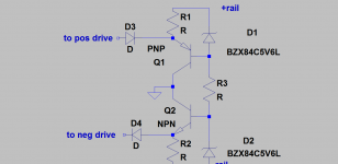
This is my thinking. It would then give a reference voltage for baker clamps off the VAS outputs.
But with the voltage rails as shown in the schematic, when the amp clips, the MOSFETs are not driven close to the rails. Could improve stability at clipping if the IPS clips first.
It could certainly be worth trying.
Also, running the FET's off a higher rail is just reducing their safe operating area and increasing dissipation, all for no gain.
Is this clipping behaviour really an issue though ? In the scheme of things it looks pretty well behaved.
Does a Schottky diode make a good Baker Clamp?
I have a variety, but no BAV, nor BAS types.
Simple fast silicone diode is enough in practice. I used 1N4148 with good result. The only backward is the low voltage of it. My experience that the low internal capacitance of the clamping diode is more important.
Sajti
I can see that 4148 is very low capacitance.
Most that specify a Baker Clamp tend to use BAV or BAS.
What parameter makes them more suitable?
Most that specify a Baker Clamp tend to use BAV or BAS.
What parameter makes them more suitable?
Most that specify a Baker Clamp tend to use BAV or BAS.
What parameter makes them more suitable?
The higher reverse voltage. Some 1N4148 is good up to 75V only, which means +/-35V power supply maximum. BAV21 is good up to 250V
Sajti
Use something like Mark Levinson.
Sajti
D1 and D2 must be set to determinate the limitation level. It must be 1-2V lower than the limiting of the VAS. R1, and R2 must set 1-2mA bias current for the transistors to make smooth switching.
Sajti
- Status
- Not open for further replies.
- Home
- Amplifiers
- Solid State
- implimenting a baker clamp