Thank You Tony.
I appreciate.
If it will ever happen to meet in person, we will taste a few of these reds together.
This photo makes me a bit teary too.
Elder people evidently turn into babies and this brings back memories from my parent’s soothing and tender when we were children and they were taking care of us during our small age frequent illnesses.
You take love, you give back love. That’s how I feel it. But this is rational.
Giving love with free will, as they did, although irrational, was (and is) soul soothing. This is what we might learn (by observation) from the elder.
Absolutely George, If I'm ever in Greece (I would love to go some time) or you are ever in Australia, or perhaps we are in some other place in the world, I would love to share a few glasses of good red! 🙂
It is interesting how memories come back from your childhood. There was a song that my mother used to sing to me as a child (perhaps when I was sick) "Morning town ride" by the seekers. I wanted to play it to my then 2 yo daughter. I found it on you tube and listened to it and couldn't help bursting into tears. No idea why! I tried to sing it to her myself, same reaction!! I suspect it was the memory of the love with which the song was sung that triggered the reaction. I cry at weddings as well (and not because I think they are making a mistake 😀) My mother has told me that she thinks I'm an Empath, I wouldn't go as far as some of the definitions, but I definitely do sometimes become a bit overtaken with emotion even when it is not directly related to me.
 Tony.
Tony.or perhaps we are in some other place in the world
If you replace the word "world" with "universe", then definitely we will enjoy a few together.😀
And according to some reliable information, They have some really good red wine up There 😛
It is really good that you are able to let your tears come out frequently.
I can't. The knot in me is very stiff.
I cry at weddings as well (and not because I think they are making a mistake )
You are at fault there (I am refering to your explanation)😀😀
Now back to the subject: Red wine
>Edit, Edit: The subject is Oscilloscope "Y Out"
Last edited:
Hi George, very good results indeed!
When I was first simulating I was looking at stuff this small and optimising to eliminate, little did I know how far from that I would be able to measure with my scope (I didn't even have a scope when I started).
The disappointment was great when I connected my scope and found that with it's maximum resolution of 2mV / div that all sorts of rf and other noise pickup made my scope trace at low frequencies quite thick and impossible to distinguish the low levels I was interested in from the wideband noise.
Then I came across your CRCRC experiment thread, and your method was a revelation 😀
I'd once again like to thank you for your efforts in doing this, it is greatly appreciated! 🙂
Tony.
I have been frustrated and totally disappointed with low level measurements.
Now, whenever I probe critical signals such low, before I form any decision about their amplitude , I record them as wav. files and then I check the frequency spectrum of them (usually through RMAA). If the original signal was say 1kHz sinusoid, I compare the height of the 1kHz frequency component with any other that is not related to it (e.g. 50Hz and it’s harmonics).
This is where a “Y Out” from the scope becomes handy.
There is a drawback though with both a (oscilloscope) manufacturer’s implemented “Y Out” and the TL074 differential amplifier circuit: They don’t isolate the sound card’s ground from the oscilloscope’s ground.
This adds one more * ground loop circuit to the measuring chain.
This is what I wanted to avoid when I thought of using an x-former as a “differential to single ended converter”.
There is a
 thought to try a x-former btn the “Y Out” and card.
 Another truckload of measurements?


* The other one is btn. the probed circuit and the oscilloscope.
>Edit: I usually get away from ground loop problems by bridging all involved "grounds" with a thick flexible wire. This is really effective if appropriately implemented (good electrical joints)
Last edited:
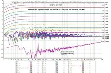
This is a revisit to the performance of the TL074 (R1=7k33).
I attach again here (att. 1) the diagram shown on post #56.
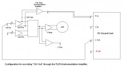
This was a representation of FR-amplitude measurements with the TL074 circuit connected as shown in block diagram on att.2.
In this diagram, it is not very clear how the 3 (i.e.: 1. oscilloscope, 2. TL074 circuit, 3. sound card) circuit commons (“grounds”) are interconnected.
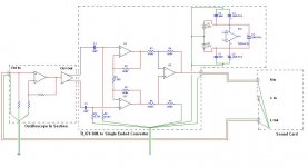
Therefore, I drew another diagram which shows this (att.3)
Here you can see the following:
The oscilloscope common is the only one that is connected to utility’s Earth.
The sound card inputs and output have their commons interconnected internally.
The sound card’s common is connected to the oscilloscope common and to the TL074 circuit common, through the interconnects outer screen.
The TL074 circuit’s common is not directly connected to Oscilloscope’s common (it’s +/-15Vdc PSU is floating), but it is electrically connected to it through the sound cards Input-Output interconnects.
I had to see how much influence would, the direct connection of oscilloscope common and TL074 common have on measurements, because that configuration would exist ,had I supplied the TL074 from the oscilloscope’s PSU.
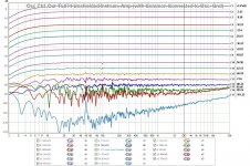
This configuration is shown on att. 4.
The measurements using this configuration are shown on att. 5 & 6.
As you can see, the acceptably quiet curve has shifted from curve C9 of att.1 to Curve C11 of att. 5 & 6. The quiet plateau has gone down by 12dB !
And this by merely connecting the TL074 circuit’s copper to oscilloscope steel sub frame by a thin 30cm long wire with 2 crocodile clips at it’s ends.
This is good news for now
Regards
George
PS. Again, curves from att. 1, 5 & 6 are from “free running” recordings. Sound card’s “L In” is not connected to card’s “L Out”, thus there is no frequency or amplitude compensation.
I attach again here (att. 1) the diagram shown on post #56.
This was a representation of FR-amplitude measurements with the TL074 circuit connected as shown in block diagram on att.2.
In this diagram, it is not very clear how the 3 (i.e.: 1. oscilloscope, 2. TL074 circuit, 3. sound card) circuit commons (“grounds”) are interconnected.
Therefore, I drew another diagram which shows this (att.3)
Here you can see the following:
The oscilloscope common is the only one that is connected to utility’s Earth.
The sound card inputs and output have their commons interconnected internally.
The sound card’s common is connected to the oscilloscope common and to the TL074 circuit common, through the interconnects outer screen.
The TL074 circuit’s common is not directly connected to Oscilloscope’s common (it’s +/-15Vdc PSU is floating), but it is electrically connected to it through the sound cards Input-Output interconnects.
I had to see how much influence would, the direct connection of oscilloscope common and TL074 common have on measurements, because that configuration would exist ,had I supplied the TL074 from the oscilloscope’s PSU.
This configuration is shown on att. 4.
The measurements using this configuration are shown on att. 5 & 6.
As you can see, the acceptably quiet curve has shifted from curve C9 of att.1 to Curve C11 of att. 5 & 6. The quiet plateau has gone down by 12dB !
And this by merely connecting the TL074 circuit’s copper to oscilloscope steel sub frame by a thin 30cm long wire with 2 crocodile clips at it’s ends.
This is good news for now
Regards
George
PS. Again, curves from att. 1, 5 & 6 are from “free running” recordings. Sound card’s “L In” is not connected to card’s “L Out”, thus there is no frequency or amplitude compensation.
Attachments
-
 1 Card Input dB Overlays.JPG191.9 KB · Views: 149
 -
 2 Ch1 Out-Instr R1=7k33.JPG37.9 KB · Views: 150
 -
 3 Ch1 Out-TL074 -Card.JPG61.4 KB · Views: 137
 -
 4 Ch1 Out-TL074 (w Common at Osc Gnd)-Card.JPG64.6 KB · Views: 141
 -
 5 Copy of overlays osc ch1 out-tl074 w common to osc gnd dBs.JPG192.4 KB · Views: 130
 -
 6 Copy of overlays osc ch1 out-tl074 w common to osc gnd mVrms.JPG193 KB · Views: 81
Hi George,
I thought i'd responded to your last post but apparently I hadn't. The idea for using the transformer to isolate the grounds was a good one, but as you have found a frustrating path to tread!
What are you using for the power supply for the TL074 if not off the oscilloscope circuit, also I assume that if the copper base for the instrumentation amp was connected to the chassis with 30 cm lead that you also have a 30cm lead to connect to the points in the circuit you are picking up from? If so then the results are even more impressive! 🙂
I finally put my SC preamp into a metal box. The reduction in noise was substantial 🙂
Tony.
also I assume that if the copper base for the instrumentation amp was connected to the chassis with 30 cm lead that you also have a 30cm lead to connect to the points in the circuit you are picking up from?
No, the signal pick-up leads are 10cm twisted pair.
What are you using for the power supply for the TL074 if not off the oscilloscope circuit
I was using an adjustable regulated bench PSU. It has voltage and current displays and a current limiting mode which is handy -safety wise- when testing circuits or operating them in a “lots of leads flying around” mode, which was the case here. 😀
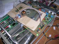
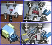
The next step was to power the TL074 circuit from the Oscilloscope PSU.
I found a convenient pick up point for +/- 12Vdc plus ground (att.1) and here we are.
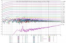
Att. 2 &3 are measurements with the TL074 circuit powered from the Oscilloscope PSU.
They are noisier compared to bench PSU measurements (att. 5 &6 of post # 64).
Probably, the bench PSU is stiffer and cleaner.
Anyway, it is clean up to C9 curve. Therefore, all the bla bla of post # 57, is applicable here too. http://www.diyaudio.com/forums/equipment-tools/189545-implementing-y-out-oscilloscope-6.html#post2607115
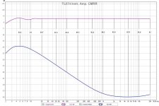
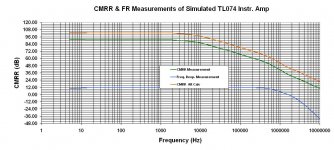
One more measurement that has to be done is the one to test the Common Mode Rejection Ratio (CMRR) of the TL074 circuit.
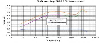
I did an auto (software assisted) measurement up to 20kHz. (att. 4)
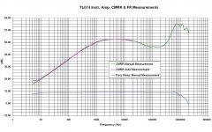
As I wanted to see what happens above 20kHz, I did a manual one, up to 2MHz.
As you can see on att. 5, results from auto and manual measurements are in agreement up to 20kHz. This give me some confidence that measurements at the higher frequencies are valid.
(Note that both measurements are with the TL074 circuit in single ended input configuration, because both the soundcard as well as my signal generator provide only single ended output.)
The reduced CMRR at the very low frequencies, may contribute to the noisy curves.
Unfortunatelly, I don’t have a true instrumentation amplifier to test it against.
I would like to hear from any member that has an experience on CMRR / frequency variation with real (Special IC) Instr. Amps.
I finally put my SC preamp into a metal box. The reduction in noise was substantial.
I saw the measurements. Congratulations 🙂
Regards
George
Attachments
-
 3 overlays osc ch1 out-tl074 unsh on osc psu mVrms.JPG182.8 KB · Views: 76
 -
 2 overlays osc ch1 out-tl074 unsh on osc psu dB.JPG182 KB · Views: 110
 -
 1 Picture 002.jpg376.9 KB · Views: 112
 -
 4 tl074 instr amp cmrr numbers.JPG114.3 KB · Views: 72
 -
 5 TL074 CMRR & FR.JPG183.2 KB · Views: 73
 -
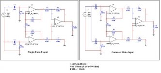 6 Test Configuration for CMRR & FR.JPG51.7 KB · Views: 81
Last edited:
haha I haven't done any more measurements on my PS since the night that I let some smoke out of one of the load resistors 🙄 so I can relate to leads flying around 😉
The results with the oscilloscope PS are also very good! The frequency response of the circuit is also very impressive! flat out to around 600Khz!! how did you do this? checking the amplitude on the scope for stepped frequencies up to 2Mhz?
I've got a bit side tracked, did some measurements on my speakers (which I'd left alone for almost a year).. one of my problems I tend to chop and change and not finish things... need to get some focus! 😉
Tony.
haha I haven't done any more measurements on my PS since the night that I let some smoke out of one of the load resistors so I can relate to leads flying around
I love BBQ myself. It is part of the hobby’s fun. 😛 But I had to be careful not doing any harm to the oscilloscope circuits (my most valuable piece of gear).
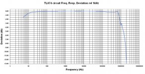
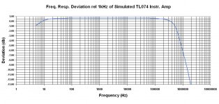
The frequency response of the circuit is also very impressive! flat out to around 600Khz!!
Almost! Att. 1 is a detailed view of the FR deviation relative to 1kHz response.
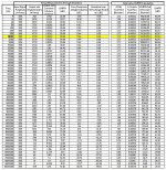
...how did you do this? checking the amplitude on the scope for stepped frequencies up to 2Mhz?
Yes. Att.2 is the data. More detailed at the HF range. 45 freq. points, 27 of them above 20kHz. 135 discrete measurements ( column 2,3 4) with the mV meter in parallel to the oscilloscope.
The rest columns are calculation results.
I feel uneasy with the CMRR results.
From what I have read, CMRR is normally high at low frequencies, dropping off as freq. goes up, the opposite from what I’ve shown.

Have I’ve done something wrong? 😕
After reading this
http://www.y-kalsbeek.demon.nl/EC1_H2_0801.pdf
I did again the calculations (columns under the “Alternative CMRR Calculation” heading) and I drew a new curve (the orange one on att.3).
It has the same shape with the green one but it is displaced higher by the amount of the Diff. Amp. Gain.
This gain I had subtracted in the green’s curve calculation.
I don’t know which is correct.
But if gain in dB should not be subtracted, this means that the higher the Diff. Amp. Gain, the better it’s CMRR. I wish some informed member chime in

Call me anytime! We’ll exchange unfinished projects 😀one of my problems I tend to chop and change and not finish things... need to get some focus!
Regards
George
Attachments

I simulated the circuit. 
Using the virtual signal generator, Oscilloscope and AC voltmeters, I took the same measurements as with the manual measurements in the previous post (plus I extended the freq. up to 10Mhz).
In the virtual world, the CMRR curve looks normal.
The same calculation formulae were used as with the manual measurements.
It seems that the problem with the peculiar CMRR curve of the manual measurements has it’s origin on the noise of the very low output signal when the inputs are connected in Common Mode.
Down with the Noise
Attachments
Last edited:
haha seems we are tarred with the same brush George 😉 Though I suspect you have more patience than me (something that is improving with age however).
I tend to be obsessed with one thing and concentrate on it a lot, but if I get distracted by something else, that becomes the new obsession, so I need to be not so obsessive for a little while to actually get things finished 😉 It does happen occasionally 😀
Nice link btw! It always amazes me what is available at the chip makers sites, Analog also has an excellent one by Walt Jung.
Tony.
haha seems we are tarred with the same brush George
Bloody brush I tell you (or is it the tarr?)🙄
I tend to be obsessed with one thing and concentrate on it a lot, but if I get distracted by something else, that becomes the new obsession,
Precisely my case. And all measurement and test condition notes from the halted projects, keep on accumulating, forming a huge pile of insufficiently documented data. A week later, this data is useless due to cryptic file names, abbreviations and such, which memory fails to comprehend. Arg 😡
Though I suspect you have more patience than me (something that is improving with age however).
“You’r talking to me?” 😀
Nice link btw! It always amazes me what is available at the chip makers sites, Analog also has an excellent one by Walt Jung.
Yes. Intrigued by that, I went downtown today and made myself a
 . Four AD620 (talking about obsession) http://www.analog.com/static/imported-files/data_sheets/AD620.pdf
"just another
diyAudio Moderator"
I just noticed that ! (or is it not new? I tend to miss the elephant)
Congratulations Tony.
I wish you all the best with your responsibilities as a moderator.

And be nice to wild animals

Regards
George
Last edited:
Precisely my case. And all measurement and test condition notes from the halted projects, keep on accumulating, forming a huge pile of insufficiently documented data. A week later, this data is useless due to cryptic file names, abbreviations and such, which memory fails to comprehend. Arg
Hi George, oh dear we are two of a kind!! I keep saying to myself I need to write better notes, I have the same problem I come back and find stuff and can't work out what it meant. That's part of the reason I post stuff here! it actually ends up better documented and I have a search facility 😉
just noticed that ! (or is it not new? I tend to miss the elephant)
Congratulations Tony.
I wish you all the best with your responsibilities as a moderator.
And be nice to wild animals
Thanks George! yes it is new, four days now 🙂 http://www.diyaudio.com/forums/introductions/191145-new-moderators.html
I'm trying but I think there may be a few bumps and bruises before I'm fully steady on my feet 🙂
Cheers,
Tony.
I'm trying but I think there may be a few bumps and bruises before I'm fully steady on my feet.
I trust you’ll feel more confident as time goes by. Try to learn from the “old hats”.
But don’t try to look like SY. I saw a picture of him once and couldn’t sleep for a week
Quote from post #68
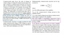
Attachment is from the link http://www.analog.com/static/imported-files/design_handbooks/5812756674312778737Complete_In_Amp.pdf
It answers both of my questions:
1. The gain should not be subtracted. Therefore, the orange curves are the correct ones.
2. The CMRR goes up with the gain.
It also points out that CMRR is a ratio, thus expressed as a number, while CMR is expressed in db.
Thus up to now I was wrongly using the term CMRR in place of CMR.😱
I did again the calculations (columns under the “Alternative CMRR Calculation” heading) and I drew a new curve (the orange one on att.3). It has the same shape with the green one but it is displaced higher by the amount of the Diff. Amp. Gain.
This gain I had subtracted in the green’s curve calculation.
I don’t know which is correct.
But if gain in dB should not be subtracted, this means that the higher the Diff. Amp. Gain, the better it’s CMRR. I wish some informed member chime in
Attachment is from the link http://www.analog.com/static/imported-files/design_handbooks/5812756674312778737Complete_In_Amp.pdf
It answers both of my questions:
1. The gain should not be subtracted. Therefore, the orange curves are the correct ones.
2. The CMRR goes up with the gain.
It also points out that CMRR is a ratio, thus expressed as a number, while CMR is expressed in db.
Thus up to now I was wrongly using the term CMRR in place of CMR.😱
Attachments
I trust you’ll feel more confident as time goes by. Try to learn from the “old hats”.
But don’t try to look like SY. I saw a picture of him once and couldn’t sleep for a week
Yes they are all very helpful 🙂 the comment about SY made me laugh harder than I have in a long time

Glad you worked out the situation with the CMR vs CMRR (and which calculation was right) I knew what the acronyms stood for but that was about it 😉
Tony.
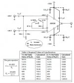
I decided to build an one IC (AD620AN) Instrumentation Amplifier http://www.analog.com/static/imported-files/data_sheets/AD620.pdf
AD620 is the only Instr. Amp. IC I found locally. It costs 5.3 Euro plus VAT
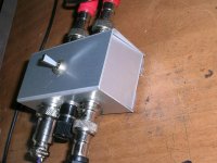
I housed it in an aluminum enclosure, for to do descent low level measurements on it.
If it will perform satisfactorily, it will be be used as a stand alone unit.
DC power supply is provided through a 4 pin plug.
Three gain steps selection is through an On-Off-On switch.
Below you’ll see the schematic and the first 😀 measurement
AD620 is the only Instr. Amp. IC I found locally. It costs 5.3 Euro plus VAT
I housed it in an aluminum enclosure, for to do descent low level measurements on it.
If it will perform satisfactorily, it will be be used as a stand alone unit.
DC power supply is provided through a 4 pin plug.
Three gain steps selection is through an On-Off-On switch.
Below you’ll see the schematic and the first 😀 measurement
Attachments
Last edited:
I did some initial overload measurements with 1kHz sinusoidal Input signal.
Fate has it, this to be my first amplifier implementation which has a variable (stepped) gain.
Therefore, this is the first time I noticed that slew limit varies with gain.
Although I trust intuition, it is not enough to deal with the subject.
Some deeper understanding is required.
So, before posting what I’ve done so far, here is a 3 part article dealing with Slew Induced Distortion (SID), which was an eye opener for me.
I hope you will appreciate it too.
http://waltjung.org/PDFs/SID_TIM_1.pdf
http://waltjung.org/PDFs/SID_TIM_2.pdf
http://waltjung.org/PDFs/SID_TIM_3.pdf
Attachments
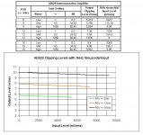
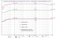
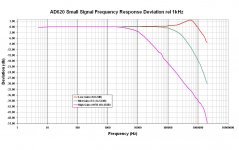
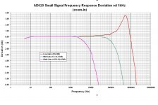
Here is the "Gain versus Frequency" manual (45 freq. points) measurement up to 2MHz. At the upper right corner, I've dropped in the same measurement from the datasheet.
Then, is the deviation from 1kHz response.
Signal Input: 1mVrms sine wave
PSU:+/-15V
Output dummy load:10kOhm
Then, is the deviation from 1kHz response.
Signal Input: 1mVrms sine wave
PSU:+/-15V
Output dummy load:10kOhm
Attachments

Last edited:
Hi George, It looks like you have been busy!! Once again nice dead bug work!
I haven't looked at the slewing articles yet, but will have to do so. So many things to learn! The measurements showing the frequency response changes with gain are very telling! This is what you were telling me right back in the beginning when I was thinking of upping the gain on the LM324!!
Looks like your results pretty much match what the datasheet shows too!
Tony.
- Status
- Not open for further replies.
- Home
- Design & Build
- Equipment & Tools
- Implementing a “Y Out” on an Oscilloscope