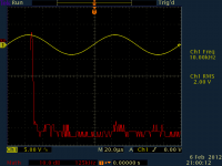
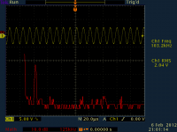
If I remember, 10kHz square wave wasn't pretty.
I believe I have the FFT software installed, at least I can hit Math and select FFT for one of the channels and it shows up as a red line on the graph.
So, what exact test setup would you suggest? Something similar to page 17 here:
http://www.cs.washington.edu/lab/facilities/hwlab/docs/mans/71034901.pdf
Also, one more question for SY when he gets back...
Why not just use a 10K attenuator and the 10K:10K transformer and not add anything in-between?
Why not just use a 10K attenuator and the 10K:10K transformer and not add anything in-between?
You can, and that will get you 95% of the best possible performance. But if you want it closer to perfect, you also have to consider the Miller capacitance of the tube and strays. I think you want to tune with a 50k pot and a 365pF variable cap. Or do what I did and tack solder a bunch of different parts in to zero in on the optimum values.
... to be clear, you mean 50K || (12.5K + 365pF). I think for now I'll just stick the pot in and the 12.5K resistor and go from there and see how it sounds.
Interesting. I am still trying to isolate the problem, it's definitely the preamp and is clearly 60 Hz sounding... But it is tough to reliably reproduce the issue.
Did you figure out the 60 Hz noise problem?
BDP
There was a slight 60 Hz hum when running amps with gain like the Aleph and F3 with my 95 dB speakers. I thought about using a regulator but the HT transformer voltage is just not high enough which means another transformer. Just not enough space in the case, so I ran the heater wiring through a bridge rectifier and CRC. With a 1 Ohm resistor the heater voltage came out to 6.25 volts. The 60Hz hum is now inaudible.
From an earlier post about noisy tubes, I tried a TUNG SOl 6SN7 and its working great. None of the EH6922 tubes have caused me any problems.
BDP
From an earlier post about noisy tubes, I tried a TUNG SOl 6SN7 and its working great. None of the EH6922 tubes have caused me any problems.
BDP
yes!
In my case it was an overloaded isolation transformer 🙁 Once rearranged my equipment it's dead quiet. Sorry for the slow response!
In my case it was an overloaded isolation transformer 🙁 Once rearranged my equipment it's dead quiet. Sorry for the slow response!
there is another thread here linking SY's article: http://www.diyaudio.com/forums/tubes-valves/210863-impasse-preamp-now-online.html#post2988095
SY, what cutoff frequency would you shoot for when choosing a capacitor before the 10K input impedance of the Impasse?
I should add the source is a phono preamp that has a rumble filter (simple RC).
I should add the source is a phono preamp that has a rumble filter (simple RC).
quick question for SY and the others that frequent this thread.
I recently built some small subs to add to my full range speakers. My chain at the moment a digital source with 4V RMS output from its balanced output (238 output impedance on the balanced outputs), to my Impasse preamp to a pair of balanced bridged F4 (0dB gain) set to 200K input impedance per leg. This is connected to my full range speakers. For analog I have a .24mV MC cartridge, 76dB gain balanced output phono with 300 ohm output impedance. My second amp that I have to use as a bass amp, is balanced input as well, 100K input impedance with 20dB gain.
My plans are to construct a active crossover that would live after the Impasse, have the ability to attenuate the signal, with an appropriate buffer. I have it all drawn up and am playing with a discrete opamp to use in the circuit and getting that ready to go. The issue is, my time is disappearing for the year and I'd love to enjoy adding the subs sooner than later.
So, suggestions? Would something like a Behringer CX2310 fit the bill? or a single box with a PLLXO in it? Quick and dirty would be great.
I think the only question is what is the maximum input the CX2310 can take. Otherwise, I could put it before my Impasse, but then the volume control there doesn't scale both speakers...
Marc, sorry I didn't see this before.
I'd aim for a 2Hz rolloff (one decade below lowest frequency of interest). Quick and dirty, I'd throw together a diff input opamp circuit with adjustable gain for the subs, run it off the output of the ImPasse, use the opamp circuit's level to balance bass and treble, then leave it alone and use the ImPasse for a master volume control. Don't know the CX2310, but I've done something like that with a DCX2496, which ran into a 4 or 6 channel balanced pre.
I'd aim for a 2Hz rolloff (one decade below lowest frequency of interest). Quick and dirty, I'd throw together a diff input opamp circuit with adjustable gain for the subs, run it off the output of the ImPasse, use the opamp circuit's level to balance bass and treble, then leave it alone and use the ImPasse for a master volume control. Don't know the CX2310, but I've done something like that with a DCX2496, which ran into a 4 or 6 channel balanced pre.
ok. thanks! i found a used CX2310 on Ebay for $60 shipped so I'll try that first.
Other than clipping the input of the CX2310 (which I'm not sure will be a problem anyways), the input impedance is 50K and I have 0.47uF capacitors in the Impasse (as I set my F4 to 200K input impedance).
Other than clipping the input of the CX2310 (which I'm not sure will be a problem anyways), the input impedance is 50K and I have 0.47uF capacitors in the Impasse (as I set my F4 to 200K input impedance).
oh boy, this CX2310 looks like it will work. I need to fix up some more XLR cables in order to get both the bass and treble amp working.
One thing I'd like that I cannot get with this, is the high pass to not be crossed over, and only crossover the bass amp. I could do something strange, like use an XLR splitter on the input and connect that straight to the full range amp though, but I'm not sure what the consequences of that would be. For now though, I'll be happy just to play with this setup.
Oh and I also got a JAN-CHY-5692 to play with as well 🙂
A couple of questions, good sirs,
Can the inputs be both balanced and single ended, or do you have to choose one or the other?
Is the gain the same when using the output single-ended? (I'm only building one F4 to begin...)
Can the inputs be both balanced and single ended, or do you have to choose one or the other?
Is the gain the same when using the output single-ended? (I'm only building one F4 to begin...)
Ordered the PCBs and Transformers from Jack, still rummaging through my
junk box, ahem, collection of various parts, to see what I can use.
Is there anything particularly important other than the CCS adjust resistor and the resistors in the split-load inverter?
junk box, ahem, collection of various parts, to see what I can use.
Is there anything particularly important other than the CCS adjust resistor and the resistors in the split-load inverter?
I can provide the following components for the Impasse -- if there's enough interest I can also get the input transformers (although they often take weeks.)
C1 2 Not used See Text
C2,5 4 100nF 630V Polypropylene
C3,C4 4 470nF 400V Polypropylene
D1,D2 4 Red LED, 1.7V Drop
NE1 2 NE2 Neon Lamp
P1 1 100K ALPS Dual Audio Taper
PCB 1 Printed Circuit Board
Q1,2 4 DN2540N5 Depletion MOSFET
R1 2 18K 1/4W Metal Film See Text
R11,12 4 15K 1W Matched to 0.1% 2 pairs
R2,9,13,14 8 1M 1/4W CMF55 Metal Film
R3,10 4 1K 1/4W CMF55 Metal Film
R4 2 12k5 2W Wirewound or Film
R5 2 300R 1/4W CMF55
R5a 2 2.7K 1/4W CMF55 Metal Film
R6,7 4 120R 1/4W Metal Film
R8 2 680K 1W Metal Film
S1 1 2 Pole, 5 Position Selector Switch
Misc 6 Molex 0.100 Inch Pin Headers
Misc 4 Nylon Spacers with nuts
Misc 2 Tube Sockets
And the following for the Impasse Maida Power Supply:
C1 1uF/600V PP
C2,3 100uF/450V
C4 47uF/450V
C9 10uF/100V
D101,102 UF4007
D103 12V 1W Zener
IC1 LM317 Regulator
PCB Printed Ckt Board
R1,2 47R 1/2W
R3 470R 1W
R4 1K 1W
R5 20K 1/4W
R6 100R 1W
R7 47R
R8/13 28K/1W
R9 200R 1/2W
R10 4.7R/0.25W
R11 270K/0.5W
R12 47K
U2 TIP50 Transistor
- Home
- Amplifiers
- Pass Labs
- ImPasse Preamplifier