for single ended you just ground the output end of the capacitor and derive the output from the cathode capacitor.
Jack,
I didn't see the price for the kit on the website. Will you send me a PM with the cost plus what you will sell input trafos for.
I didn't see the price for the kit on the website. Will you send me a PM with the cost plus what you will sell input trafos for.
"That being said, I reworked the boards to amend the error I'd made with the Depletion MOSFETs and straightened out the layout a bit. The results are pretty good. In single ended mode with 10K load the THD% with 2.828V out is 0.0037%. (SY said in the article: "better than 0.01%). I found that Electro-Harmonix worked best, but YMMV. I also substituted 1u/400V on the output as I used the rest of my 0.47u/400V on another project."
Interesting I had purchased a board from you a few months ago and had asked if you had made these changes. I never received any answer from you and was shipped the old board. I have not put it to use yet ant chance of exchange?
Thanks
Bill
Interesting I had purchased a board from you a few months ago and had asked if you had made these changes. I never received any answer from you and was shipped the old board. I have not put it to use yet ant chance of exchange?
Thanks
Bill
The changes in the board were to allow utilization of the Cinemag transformer, (the original used the Sowter's), to correct the error on the orientation of the CCS MOSFETs, and to allow for easier insertion of a resistor to adjust the CCS to 8mA per side.
I also spent some time on the ergonomics of the ground returns which made them look a bit prettier.
All this being said, the boards are functionally the same -- you have the benefit that I personally soldered in the depletion MOSFETs and adjusted the bias resistors such that the CCS delivers 8mA.
If I priced out the time that I spent designing the boards and amortized the cost of my software, etc., etc. they would be much more expensive than the couple of bux I am charging for them. All I wanted to derive from the project was a couple of boards for myself and, by ordering in quantity availing all the group members of a knock down price on a pre which rivals those costing 3 or 4 kilo-bucks.
Outputs
When you speak of single-ended outputs , do you mean using rca jacks as opposed to xlr's ?
When you speak of single-ended outputs , do you mean using rca jacks as opposed to xlr's ?
When you speak of single-ended outputs , do you mean using rca jacks as opposed to xlr's ?
I guess you could use BNC connectors 🙂
If memory serves correctly, XLR Pin 3 on the PCB is connected to the cathode output cap. This would go to the center of the RCA jack, and XLR Pin 2 would go to the ground ring.
In balanced mode I've run the output over 40V pk-pk and nothing smoked. I would bet SY has run it up even more.
XLR/RCA
 Here are a couple things I had found while looking into the using XLR preamp outputs with RCA inputs to a poweramp > http://www.rane.com/pdf/ranenotes/Grounding_&_Shielding_of_Audio_Devices.pdf
Here are a couple things I had found while looking into the using XLR preamp outputs with RCA inputs to a poweramp > http://www.rane.com/pdf/ranenotes/Grounding_&_Shielding_of_Audio_Devices.pdf
Last edited:
I believe that the first wiring you illustrate probably has best rejection or RF Interference. Best advice I can give is to keep you cable runs as short as practicable. It doesn't matter what the silkscreen is marked as long as you know that XLR3 is the cathode of a cathode-follower in single ended. I think that SY measured single-ended as he doesn't have a true balanced-in on his test apparatus.
Actually, I do have a balanced in on my test setup. 😀 I've measured the circuit both ways, which is why I have some confidence in recommending it as a single-ended line stage if the plate output from the cathodyne is grounded.
I started a few experiments in pushing the output swing before I left town (I'm in Western New York at the moment). When I get back, I hope to finish that up so the boards can be used to make a driver stage for a 6L6-class power amp.
I started a few experiments in pushing the output swing before I left town (I'm in Western New York at the moment). When I get back, I hope to finish that up so the boards can be used to make a driver stage for a 6L6-class power amp.
Take a bushel of apples back to TX when you leave. The XYL and I stayed in a lovely B&B just a few miles from the home of "Welch's Grape Juice" last summer. Lovely drive along Lake Ontario from Rochester.
My wife is bringing back apples and Bully Hill wine. I'm bringing back some Rioja I had stashed in NYC.
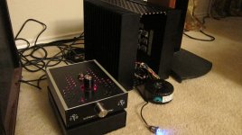
Well, here's where I am going -- you can guess what's next:
An externally hosted image should be here but it was not working when we last tested it.
Power amp!
For extra swing at the expense of somewhat higher (but still low) source Z, you could get rid of the voltage divider between stages and use an ECC81 for the phase splitter.
For extra swing at the expense of somewhat higher (but still low) source Z, you could get rid of the voltage divider between stages and use an ECC81 for the phase splitter.
Something more prosaic, an amplifier for my Stax Lambda's -- they need over 400V bias:
An externally hosted image should be here but it was not working when we last tested it.

- Home
- Amplifiers
- Pass Labs
- ImPasse Preamplifier