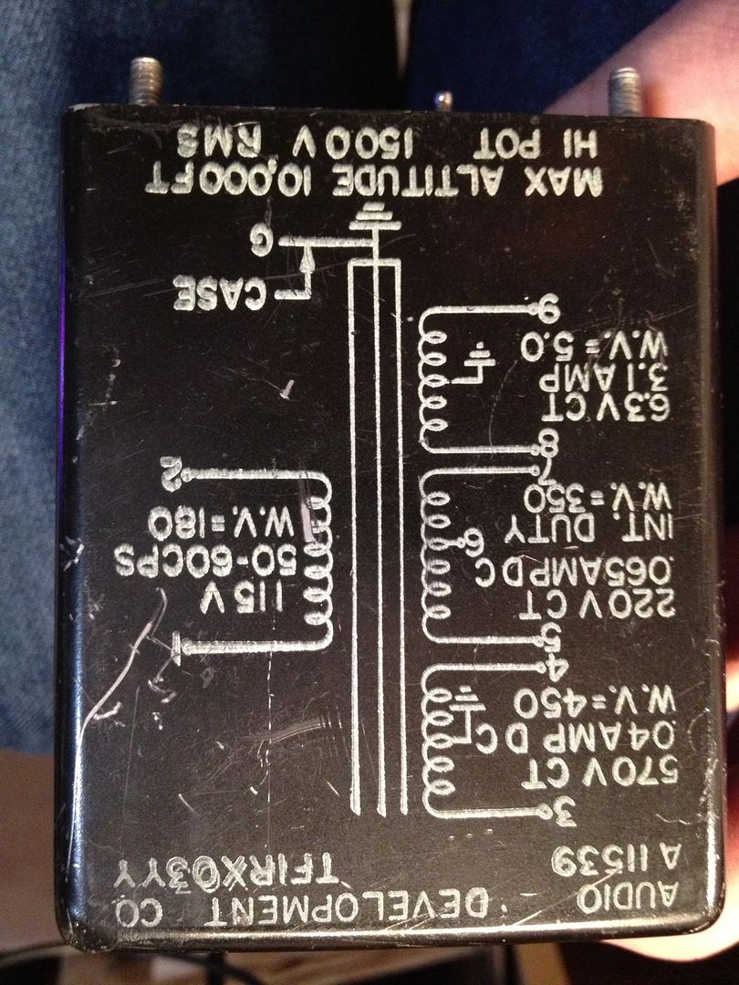
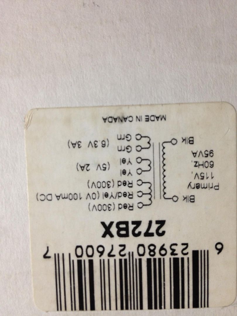
I have 2 transformers that could work - Which do you think would be better?
Both are not ideal - the potted one is a little shy on voltage, the Hammond has no filament CT...
I just noticed this about the potted one - if you look at the schematic, and the pins confirm it as well, the CT of the HV and the filament is the case... That's weird...
Both are not ideal - the potted one is a little shy on voltage, the Hammond has no filament CT...
I just noticed this about the potted one - if you look at the schematic, and the pins confirm it as well, the CT of the HV and the filament is the case... That's weird...
Last edited:
Top one has a case shield which is useful -- the Allied Transformer SY used Allied 6K3VG also had one.
Top one has a case shield which is useful -- the Allied Transformer SY used Allied 6K3VG also had one.
And the fact that the CT of the HV and FIL windings is that same shield is no problem? I ask only because I haven't seen that before.
If it's potted then there's be no way to disconnect it!
There are other ways to get the filament at the potential necessary.
There are other ways to get the filament at the potential necessary.
Im needing to make one more order to get all the parts...the local electronics surplus has most of the stuff, but I still need to fill it out.
A couple questions,
What voltage NE-2? I'm not sure if the ratings are the strike voltage or max operating...
Is there any issue using a stepped attenuator? I have a 100K noble that I'm planning on using, but I'm still curious...
Are there any 'gotchas' in building this? Anything not obvious?
A couple questions,
What voltage NE-2? I'm not sure if the ratings are the strike voltage or max operating...
Is there any issue using a stepped attenuator? I have a 100K noble that I'm planning on using, but I'm still curious...
Are there any 'gotchas' in building this? Anything not obvious?
Neon is not critical, it's just for start-up protection- the lower the voltage, the better.
Main thing is to keep the bodies of the grid and gate stoppers close to the grids and gates. Otherwise, it's a pretty easy build.
Main thing is to keep the bodies of the grid and gate stoppers close to the grids and gates. Otherwise, it's a pretty easy build.
They could be closer, but I've built two of Jack's boards and they both worked perfectly. So I can't really complain. 😀
I have another question that I just cant get my head around...
When running a F4 as mono you get 50W from a single-ended connection, but 100W from a balanced. The Rails are not any higher, and you have the same amount of PSU, so how can you get a doubling of power?
😕😕😕
I'm sure with a good explanation it will become obvious...
When running a F4 as mono you get 50W from a single-ended connection, but 100W from a balanced. The Rails are not any higher, and you have the same amount of PSU, so how can you get a doubling of power?
😕😕😕
I'm sure with a good explanation it will become obvious...
The 100W figure in balanced mode is for an 8 Ohm load. Operating in mono parallel you can also get 100W driving a 2 Ohm load. Connecting the RCA inputs in parallel increases the load handling capability.
OK, thanks. When you have one amp, the other end of the speaker is at zero volts while the first one swings up and down. When you have two amps, the other end of the speaker swings down while the first one swings up and vice versa.
I have another question that I just cant get my head around...
When running a F4 as mono you get 50W from a single-ended connection, but 100W from a balanced. The Rails are not any higher, and you have the same amount of PSU, so how can you get a doubling of power?
😕😕😕
I'm sure with a good explanation it will become obvious...
You just about double the voltage swing at the output.
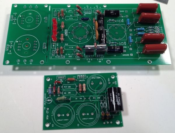
I finally got some tube sockets and a couple other little things to finish stuffin the PCB, and am quite close to attaching it to a piece of wood, um... I mean installing it into the testing and analysis fixture, and lighting this candle.
I am confused by a few things and could use a little clarification -
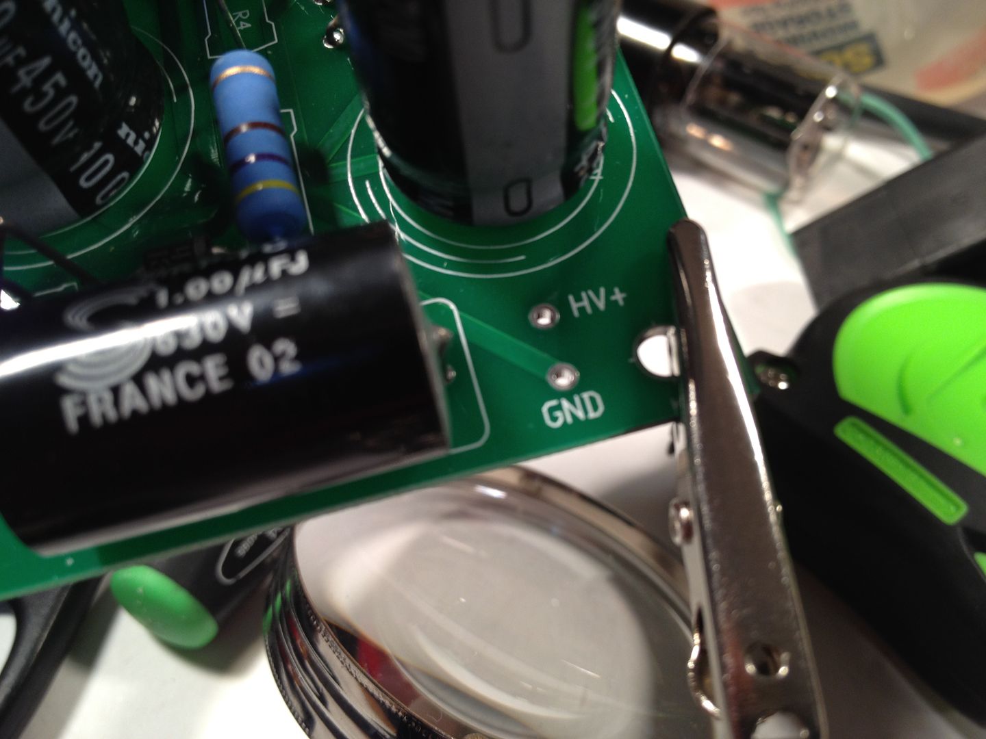
There is only one output on the regulator PCB...
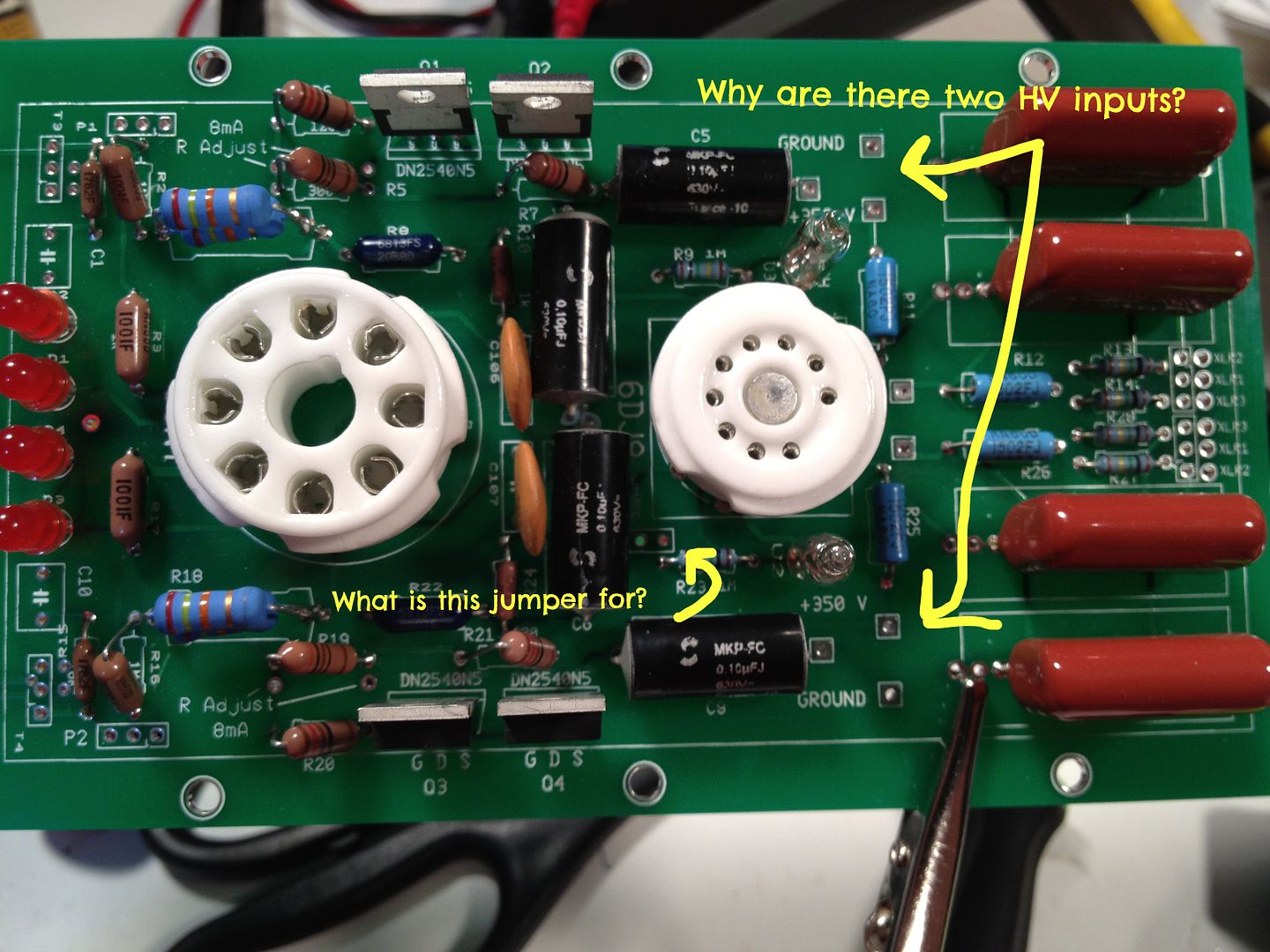
But two HV inputs, and grounds, on the amp board... ??
Also, what's that little jumper for? These seem to be a revised board and I have never seen any info on them...
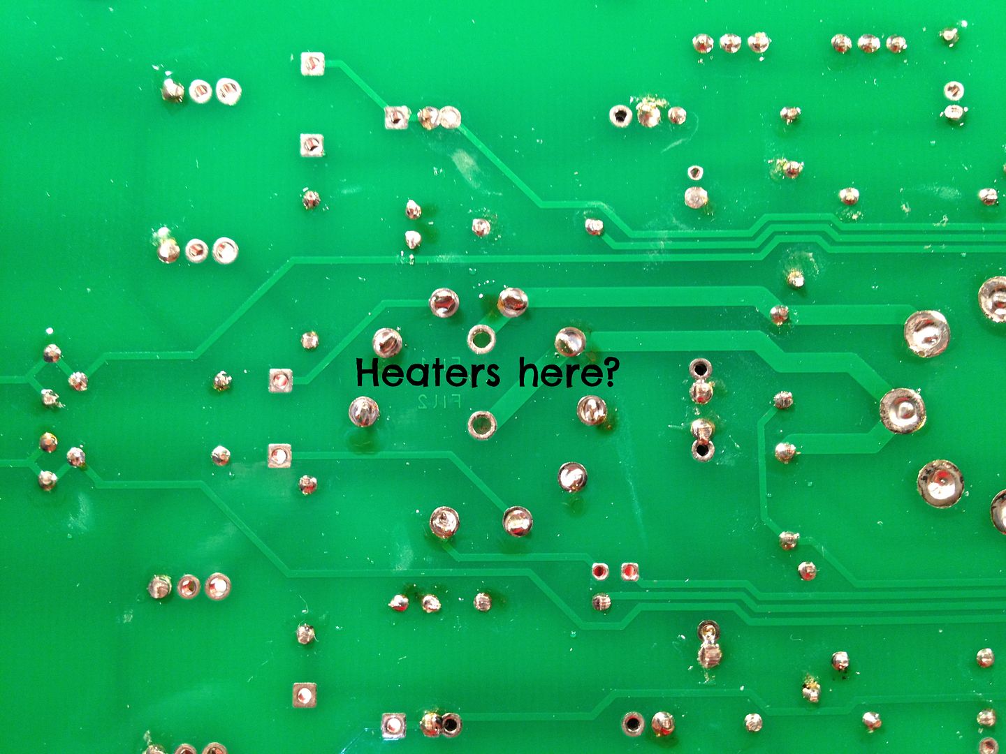
Attach heaters here, but still take the heater CT to the PSU board?
Anything else worth mentioning before applying power?
I am confused by a few things and could use a little clarification -
There is only one output on the regulator PCB...
But two HV inputs, and grounds, on the amp board... ??
Also, what's that little jumper for? These seem to be a revised board and I have never seen any info on them...
Attach heaters here, but still take the heater CT to the PSU board?
Anything else worth mentioning before applying power?
1) There are 2 HV inputs -- for you to regulate the 2 halves separately if you want. You'd need 2 Maida pcbs for this option. I use only one and the 2 HV nodes on the preamp board are tied together.
2) The jumper is there if you want to connect the shield of the tube to ground. Mine is open
3) Yupp, heaters go there -- twist the wires together.
4) I have C1 and C10 jumpered. I didn't find that playing with values benefitted much.
2) The jumper is there if you want to connect the shield of the tube to ground. Mine is open
3) Yupp, heaters go there -- twist the wires together.
4) I have C1 and C10 jumpered. I didn't find that playing with values benefitted much.
Look at post #454. That's what I did to mine. Still my favorite preamp. Every once in a while I will swap in another, but that doesn't last long.
Jack, BDP thanks for the info, that clears some things up. 🙂
Jack - Just to verify, the CCS Fets don't have to have their legs crossed on this version of the PCB?
Jack - Just to verify, the CCS Fets don't have to have their legs crossed on this version of the PCB?
stereo
Hello,
I don't have much experience with tubes, so sorry in advance for my lame questions...
It looks like signals for both channels (left and right) are passed through the same tubes. How does it affect separation between channels?
Hello,
I don't have much experience with tubes, so sorry in advance for my lame questions...
It looks like signals for both channels (left and right) are passed through the same tubes. How does it affect separation between channels?
- Home
- Amplifiers
- Pass Labs
- ImPasse Preamplifier