yeah...try not to loop grounds around...it creates a big antenna that picks up noise...and twist AC lines...
Could someone post a picture of the inside of the amp chassis, looking at the input jacks, back far enough to see the trans and supply caps?
Cheers, John
Cheers, John
simboo said:
Heheh, that was going to be my last resort, as it seems to be the most expensive! however, I think I may as well do it now by the sounds of it as I have the exact same module in a mono subwoofer setup in another room, and it exhibits no problems at all.
I guess I've gotten to the stage that the only thing left that it could be is the two amps sharing one case..
I somehow missed this answer: didnt you say that you already have 2 toroids, separate caps, etc? Why should it be more expensive cutting 2 or three wires?
Cheers
Andrea
Hi Janne and Andypairo and others!
I have own filter capacitors for both channels too!
Can you Janne draw my schematic picture where that ripple current flows, because I'm not sure did I understand right your description. Anyway, its sounds reasonable to me.
I thinking that other PSU too, but its quite expensive cure for this hum problem.
But on the other hand, another PSU enable make this amplifier to double mono. 😛
Sorry Andrea , but what Krijstian site you mean?
Simboo:
I guess you should think also that double mono procedure because you have own PSU's for both channels, so you must fully separate those channels -> no common start points.
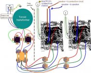
Below is my wirings!
I have own filter capacitors for both channels too!
Can you Janne draw my schematic picture where that ripple current flows, because I'm not sure did I understand right your description. Anyway, its sounds reasonable to me.
I thinking that other PSU too, but its quite expensive cure for this hum problem.
But on the other hand, another PSU enable make this amplifier to double mono. 😛
Sorry Andrea , but what Krijstian site you mean?
Simboo:
I guess you should think also that double mono procedure because you have own PSU's for both channels, so you must fully separate those channels -> no common start points.
Below is my wirings!
Attachments
Should I have some filter in inputs?😕
Original Elektor instructions does not mention anything about this but some amplifier have somekind capacitor-resistor connected to inputs.
Original Elektor instructions does not mention anything about this but some amplifier have somekind capacitor-resistor connected to inputs.
General rules (mine anyway)
Always twist pos and negs together..on supply rails, input of bridges, and speaker outs..can't tell if you did.
Using toroid, so it's not picking up roid hum..It looks like your oscillating because the input grounds are forming a loop and interacting with your outputs..
Try bringing left input shield at right angle to board, under it, over to right one..bundle both physically together to inputs jacks.
Cheers, John
Damn... Andypairo, your answers are quicker than my mind 😀
Yes, only right channel amplifier board should be rotated 180 degrees.
I do not have done that twisting thing.
I must try it too, but I guess this hummm/buzzz comes somewhere else.
Anyway... I must change chassis for this Crescendo because those heatsinks are too small and they get very hot. Hurts when touch.
But anyway, all tips and hints are wellcome because someday I will change that chassis and same problems will be ahead.
I must try that Aleph wiring thing....
Andypairo said:
Does your drawing represent the physical placement of trafo and boards?
Yes, only right channel amplifier board should be rotated 180 degrees.
I do not have done that twisting thing.
I must try it too, but I guess this hummm/buzzz comes somewhere else.
Anyway... I must change chassis for this Crescendo because those heatsinks are too small and they get very hot. Hurts when touch.
But anyway, all tips and hints are wellcome because someday I will change that chassis and same problems will be ahead.
I must try that Aleph wiring thing....
But hey.... where is my starpoint anyway?
On main filter capacitors near bridges or centre piece of both channels bypass capacitors?
I guess.... no... I don't only guess, I know that starpoint should be separated from main capacitors centre piece with short and thick wire.
But is that zero line wiring from main capacitors to both channel bypass capacitors done right way?
And how about that my earlier question about input filter or how it should be call ( I mean that parallel capacitor and resistor connected from input RCA ground to chassis)?
Eccu,
This how I figured it out:
So as you can see, the ripple current flows thru RCA grounds to the another channel filter capacitors, and acts just like parallel unintended conductor.
Of course, this requires that RCA grounds are connected together at source end, where you plug them.
Regards,
Janne
This how I figured it out:
An externally hosted image should be here but it was not working when we last tested it.
So as you can see, the ripple current flows thru RCA grounds to the another channel filter capacitors, and acts just like parallel unintended conductor.
Of course, this requires that RCA grounds are connected together at source end, where you plug them.
Regards,
Janne
jahonen said:Eccu,
This how I figured it out:
An externally hosted image should be here but it was not working when we last tested it.
So as you can see, the ripple current flows thru RCA grounds to the another channel filter capacitors, and acts just like parallel unintended conductor.
Of course, this requires that RCA grounds are connected together at source end, where you plug them.
Regards,
Janne
I don't think any ripple current is getting to that loop...I believe ripple is just in the roid/bridge/cap loop.
But that loop certainly is the one I am worried about..
Eccu: I see that andy's schem has both single and diff input setups, where you are using the single..You draw the inputs as going to two points on the board, where andy has G tied to minus for single ended input..Are they the same circuit boards?
Cheers, John
![copia di schema[1].jpg](/community/data/attachments/18/18650-b752393958352a2584577b7144155672.jpg?hash=t1I5OVg1Ki)
sully said:
I don't think any ripple current is getting to that loop...I believe ripple is just in the roid/bridge/cap loop.
But that loop certainly is the one I am worried about..
Cheers, John
It does not, in special case that all ripple currents are exactly same and in opposite phase. But, if any deviations occur (f. ex. filter capacitors do not have exactly same capacitance, which is usually the case because of the tolerances), then the ground potentials will be slighty different between channels due to finite IR drops => loop current starts to flow, creating that hum.
That IR drop determines parasitic ripple loop current that flows through the RCA ground. Of course, much larger ripple flows in the loop you describe. But, as interconnect resistance is much higher in signal path (and signal path is not really suitable for large currents), relatively large hum is created.
To avoid that loop, separate signal ground is required to star points. Maybe point where power and signal grounds are connected together at PCB can be broken, and signal ground connected from there to central ground point (i.e. main filter capacitor ground point, where smaller filter cap grounds connect also) with separate wire. I believe this is the idea which is used in aforementioned Aleph ground scheme.
But, this is only speculation, it might be considerably more difficult in reality. Amplifier HF instability is my main concern.
If this kind of difficulty arises easily, just imagine how difficult it is to build, say a six channel amplifier 😀
Regards,
Janne
jahonen said:
It does not, in special case that all ripple currents are exactly same and in opposite phase. But, if any deviations occur (f. ex. filter capacitors do not have exactly same capacitance, which is usually the case because of the tolerances), then the ground potentials will be slighty different between channels due to finite IR drops => loop current starts to flow, creating that hum.
That IR drop determines parasitic ripple loop current that flows through the RCA ground. Of course, much larger ripple flows in the loop you describe. But, as interconnect resistance is much higher in signal path (and signal path is not really suitable for large currents), relatively large hum is created.
To avoid that loop, separate signal ground is required to star points. Maybe point where power and signal grounds are connected together at PCB can be broken, and signal ground connected from there to central ground point (i.e. main filter capacitor ground point, where smaller filter cap grounds connect also) with separate wire. I believe this is the idea which is used in aforementioned Aleph ground scheme.
If this kind of difficulty arises easily, just imagine how difficult it is to build, say a six channel amplifier 😀
Regards,
Janne
I don't agree with your ripple thing..the large ripple currents will run through the caps/bridge and 'roid..a supply imbalance will just offset the rails.. But I concur with your star ground..
I had no such problems with the 6 channel I built..but I only used LM 3876t's, so the amp really wasn't a hot one BW wise..
I think Andy's mod should work..
Cheers, John
Yes, Andy's modification is just how I meant it, but he grounded another way around (from RCA end), but same idea. It should do the job.
Regards,
Janne
Regards,
Janne
Thanks Janne. I did understand right that loop from your earlier description, but that picture tells more than thousand words. Now I am happy 😛
John, what you mean You draw the inputs as going to two points on the board, and about this Are they the same circuit boards?.
Thanks again Andypairo. Seems reasonable to me. I must try that and see if that works before I dismantle whole amplifier and re-build it to another bigger case.
I hope I can send some pictures soon.
Thanks for everyones help, I have wired up the grounds again after reading Andypairos post, and all is good!
I am very happy with it now. Finally no buzzing when two RCA's are connected!.
The problem was that the 0V line from the caps to the PCB should have gone "caps 0V >> chassis ground >> PCB ground" now it works perfectly. yay!
I am very happy with it now. Finally no buzzing when two RCA's are connected!.
The problem was that the 0V line from the caps to the PCB should have gone "caps 0V >> chassis ground >> PCB ground" now it works perfectly. yay!
I suggest another grounding scheme based on star-ground principle
Each channel should have 3 different grounds independently connected to the star point :
- Input signal ground
- Channel signal ground
- Channel decoupling ground
Input signal ground should not be connected to signal ground on the circuit board of each channel
Signal ground [the one used for reference in feedback, etc...] and decouplig ground [the one used for all supply decoupling capacitors] should be independent on the circuit board of each channel and only lousy coupled by a 68Ohm or so resistor [or maybe a 10nF or so capacitor] to compensate high wiring impedance at RF
Each signal ground and decoupling ground should be connected to the star point with an independent wire
Apart from ground loops, induction is another source of noise and distorsion and should be avoided minimizing area of current loops
I suggest taking each output speaker ground from star point
The four power wires from each channel should go twisted to supply filter capacitors [+Vcc ,-Vcc , decoupling ground, speaker output], and then, speaker output and speaker ground wires should go twisted to output binding posts or connectors
As an alternative, speaker ground may be taken from each channel circuit board, twisting +Vcc, -Vcc and decopuling ground to the supply capacitors and also twisting speaker output with speaker ground to the output connectors
Induction can be measured simply connecting a loop of wire to oscilloscope probe, making the amplifier driving a low impedance load at full power and moving the loop probe near the wiring, channel circuit board, supply transformer, etc...
Twisting current go and return wires you get very low induced voltages, being dominant the magnetic field created in the typical output inductor [that in my opinion allways should be a iron-powder toroidal core to minimze stray magnetic field]
PD: Sorry for my bad english
Andypairo said:Eccu, I'd re-wire this way.
Please let me know if it works.
Cheers
Andrea
Looking at that layout, I see a potential problem. The speaker current runs through the blue wire between PCB and supply cap grounds. That means there will be a voltage between PCB gnd and supply cap ground. Since there are other grounds (from supply and RCA) to the PCB gnd, there will be ground loops. They are not the cause of hum, but may ruin the sound and/or lead to instability. Route the speaker returns directly to the gnd between the supply caps. That way the current through the big blue one will be much less, making the supply cap gnd and PCB gnd more equal. Better yet, leave the speaker return as is, run each supply cap gnd with separate wires to the PCB gnd, that will give you true star ground.
Jan Didden
- Status
- Not open for further replies.
- Home
- Amplifiers
- Solid State
- I'm gona crazy cause of hum