Hi members.
Sharing this new proto of amplifier made with...............IGBTs. Lot of people will say "cannot works! Mosfets are better" Yes, but, why not try.
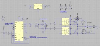
Structure used is build around TL494 working for PWM generation and high current opto drivers (TLP358) driving high speed IGBTs (GW30NC60)
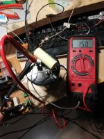
At this step, with 110Vdc supply, it reach 550W (29Veff) into 1.5ohms load.
Will try to increase little more output power (to reach IGBT maximum rating).
Sound is quite good, better than some chinese amplifiers 😀
Feel free to try it.
Sharing this new proto of amplifier made with...............IGBTs. Lot of people will say "cannot works! Mosfets are better" Yes, but, why not try.
Structure used is build around TL494 working for PWM generation and high current opto drivers (TLP358) driving high speed IGBTs (GW30NC60)
At this step, with 110Vdc supply, it reach 550W (29Veff) into 1.5ohms load.
Will try to increase little more output power (to reach IGBT maximum rating).
Sound is quite good, better than some chinese amplifiers 😀
Feel free to try it.
Attachments

Which is the frequency of the PWM? This is the key point. IGBT's are intrinsically low, in fact "High speed" units for arc welders and ultrasonic cleaners are rated up to 33KHz, very bad for audio.
Which is the frequency of the PWM? This is the key point. IGBT's are intrinsically low, in fact "High speed" units for arc welders and ultrasonic cleaners are rated up to 33KHz, very bad for audio.
I designed a analogue amplifier using IGBT's and it sounded ok.
But analogue (I suspect linear amp) doesn't switch at higher ultrasound frequencies, my lord.
But even then 20KHz was pushing things a bit.
I have seen analogue amps with bandwidths up to 200KHz.
Last edited:
Ok, guy, but respectfully, we are speaking of different thinks. Linear amps do not need the large and continuous voltages changes that a well designed class D (PWM or switching amps) needs. A medium power class D amp need to switch, say, 200V in nanoseconds or still better, picoseconds. A linear class A or AB doesn't.
Class D are switching at ultrasound frequencies still with no signal, while a linear, only a small DC current flows.
Class D are switching at ultrasound frequencies still with no signal, while a linear, only a small DC current flows.
Ok, guy, but respectfully, we are speaking of different thinks. Linear amps do not need the large and continuous voltages changes that a well designed class D (PWM or switching amps) needs. A medium power class D amp need to switch, say, 200V in nanoseconds or still better, picoseconds. A linear class A or AB doesn't.
Class D are switching at ultrasound frequencies still with no signal, while a linear, only a small DC current flows.
On full power the amplifier is switching very quickly.
Ok, guy, but respectfully, we are speaking of different thinks. Linear amps do not need the large and continuous voltages changes that a well designed class D (PWM or switching amps) needs. A medium power class D amp need to switch, say, 200V in nanoseconds or still better, picoseconds. A linear class A or AB doesn't.
Class D are switching at ultrasound frequencies still with no signal, while a linear, only a small DC current flows.
> 270 khz is required for clear natural High Quality audio 20 - 20khz
otherwise Class D amp sound poor like compressed, metallic.....
IGBT is for high power Class D Subbass ok
IGBT in N-Channel analog PA amo (not Class D) is a BEAST and workhorse,
will outperform any bipolar amp if have good circuit design
With 160V Class AB + Class TD you can outperform Class D
Last edited:
You need to know the Limits fpr Class D
The Limits for Class D are between 90 to 120 V DC Rail.
you need to bridge > 120V DC Rail
Class AB + Class TD no need to bridge 180 V DC no problem
Class TD Rail switcher work with about 50 khz. easy for most IGBT and Mosfet at high Voltage,
and most of 600V IGBTs will working in Class AB Section with High audio quality and without secondary beakdown problems v/s bipolar
Last edited:
The Limits for Class D are between 90 to 120 V DC Rail.
Please tell where did you get this information.
fun thread it seems xD
.. maybe some measurments of said amplifier?
Of course!
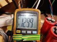
Pic1 : supply voltage
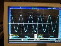
Pic2 : Sinus rendering
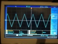
Pic3 : Triangle rendering
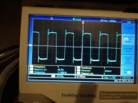
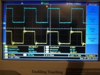
Pic4 : Square rendering
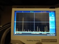
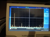
Pic5: FFT sinus 5kHz
Pic6: FFT sinus 10kHz
Pic7: Load DC resistance
Pic8; Output voltage before LC filter (thanks to the snubbers 🙄)
So quite good result; just to much 3rd harmonic, but sounds (very) good.
I'm aware that is not SuperHyperMegaPro HiFi of the dead, it's just a simple experience to show that we can build amplifier from parts used in washing machines...
Attachments
-
 IMG_20191227_200219.jpg278.4 KB · Views: 317
 -
 IMG_20191227_195634.jpg182 KB · Views: 260
 -
 IMG_20191227_195506.jpg183.8 KB · Views: 362
 -
 IMG_20191227_195940.jpg201.6 KB · Views: 360
 -
 IMG_20191227_195924.jpg218.2 KB · Views: 478
 -
 IMG_20191227_195739.jpg209.4 KB · Views: 403
 -
 IMG_20191227_194837.jpg212.4 KB · Views: 402
 -
 IMG_20191227_194828.jpg222.4 KB · Views: 264
Last edited:
Please tell where did you get this information.
For Fullrange you will need >270 Khz otherwise amp will sound poor
Try to find 500 V Mosfet to handle ?
Switching loss and idle power consumption 160 V DC ?
Class D very inefficient at low output power with 160 V DC Rail
Easy with 90 V DC and bridge to get 2500W
awesome, not all is about sound quality, some forget electronics and fun parts of this hobby.. please do update with stuff you do with it.. happy holidays
Nyquist-Shannon sampling theorem => minimum switching frequency : 40kHz. I still want to know how you calculate 270kHz.For Fullrange you will need >270 Khz otherwise amp will sound poor
Got it, 20N50 & IRFP460 but don't want to use them.Try to find 500 V Mosfet to handle ?
Extract of 20N50 datasheet
RDS(on) < 0.27Ω @ VGS=10V, ID=10A
So @ 20A, Conduction losses = 20Ax20Ax0.27 = 108W
Now 30NC60 :
VCE(sat) Collector-emitter saturation voltage VGE= 15 V, IC= 20 A VGE= 15 V, Typ 2.1V, Max 2.7V
Same idea : 20x2.1=42W, in worst case 20x2.7=54W
Good question, to be honest I don't know and I don't care. Seriously, they should be 5 to 6W switching losses (50mA), but I repeat : I don't care, not my goal to made the best efficient amp.Switching loss and idle power consumption 160 V DC ?
See end of previous answer.Class D very inefficient at low output power with 160 V DC Rail
One more time, I'm not "purist", I made electronics for fun.
Last edited:
Someone else's subjectivism...
PA Discrete Class D Amplifier Schematic
The design is UCD self oscillating with post filter feedback. 270K is presumably the zero output switching frequency.
PA Discrete Class D Amplifier Schematic
The design is UCD self oscillating with post filter feedback. 270K is presumably the zero output switching frequency.
- Home
- Amplifiers
- Class D
- IGBT Class D amplifier