I can't speak to the hum issue, but it might help. ostripper may be able to predict, as he seems to have experience with the offset adjust scheme or a similar variant.
It would work good , that is still a lot of devices (for that performance level). Besides the (too many) FET's it the same design as the Leach amp or my
"Hellraiser" (CFA leach amp). It even uses that odd FET hawksford Cascode VAS. Yes <1mV offset - sometimes uV level !!
BTW - NO hum
"Hellraiser" (CFA leach amp). It even uses that odd FET hawksford Cascode VAS. Yes <1mV offset - sometimes uV level !!
BTW - NO hum
Attachments
Why is that? I see only one inversion in the DC loop, so the loop polarity is correct.If the DC servo really is as shown, I would expect U1 output to be stuck on a supply rail. R49 should be connected to ground rather tied at R50, C30.
If the DC servo really is as shown, I would expect U1 output to be stuck on a supply rail. R49 should be connected to ground rather tied at R50, C30.
I'm embarrassed, but I must withdraw this comment. Maybe my eyes are failing, but I thought the error amp was a differential integrator, i.e. non-inverting integrator. But it's not. Opamp plus input is grounded--- a simple pole followed by inverting integrator. 🙁
ARC make no secret that this amp is “voiced” (my word there). I for one would like to hear it compared to a high feedback / PPM style amp. may not like it but like to hear 🙂.
Good point--it's a regular LTP without Q5 and Q8, and they turn it into a long tailed trio.It looks slightly more conventional when you ignore Q5 and Q8, then they simply take the output current from one side of each input differential pair. Q5 and Q8 are needed because of the differential input, so the differential-to-single-ended conversion and input differential pair are intertwined.
Without overall feedback, the DC servo would have a bandwidth of roughly 1/6 rad/s, 0.026 Hz, so it would take about 30 seconds to settle within 1 % of the initial offset. The overall feedback probably makes it even slower, and it gets slower again when you push the mute button.
"Voice the input" , leave the amp PPM. The "voice" stays very consistent. Same as on the arc , it's hawksford would soft clip. So , voiced at overload.ARC make no secret that this amp is “voiced” (my word there). I for one would like to hear it compared to a high feedback / PPM style amp. may not like it but like to hear 🙂.
Yep. My DAC has that function. Still, interesting amp /post so thanks to the OP 👍Voice the input

Q15 and Q16 appear to be drawn wrong.
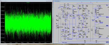
The voltage regulation is applied to only part of the front-end. Combined with little negative feedback, the result is hum.
I suspect a lot of the sound of this amplifier is due to the high (~0.8 ohm) output impedance. The effect can be mimicked on a good amplifier by adding a resistor in series with the speaker.
Ed
Q15 and Q16 appear to be drawn wrong.
They look like normal FET current sources to me: N-channel depletion MOSFETs with a resistor from source to gate to give some series feedback.
162/3.3 = 49.1, is that really much different from 47 ?The feedback netwoek 162k:3k3 could easily be changed to a more conventional 47k:1k
TBH I was a bit disappointed to see a GNFB loop at all, with that number of complimentary output transistors I'd have hoped for a more imaginative design. Leaving them out of the feedback look, perhaps as part of a darlington, would also enable the low level signal earth to be decoupled from the speaker return path perhaps.
I like the FETs on the input, probably helps the sound, NFB only really works well on a linear system IIRC, so perhaps this makes it sound nicer.
Thank you for all the insightful feedback of this somewhat quirky design. I'm curious, aside from scoping the outputs for cutoff, can one assume an estimate of class A power via the amp's AC input power draw at idle vs that at full power? I ask as ARC specs 150 watts at idle and 390 at rated output. With these two numbers given, any estimate of what class A power might be before switching to A/B? Even at 50% efficiency, would a guess of 20 watts be overshooting the realm of possibility considering a rating of 100 watt @ 8 ohm full power? Both ample heat sinks also maintain a toasty 114 degrees Fahrenheit at idle.
Last edited:
Taking the bias voltage across emitter R from bottom left of schematic.
8*.023V/.2R=.92A
.92A^2*8R=6.77W
8*.023V/.2R=.92A
.92A^2*8R=6.77W
I think it should be a useful measure, yes.can one assume an estimate of class A power via the amp's AC input power draw at idle
Nice it's got split PSU for the driver and output transistors, stops the driver PSU rails dancing around with the music 😀
So assuming it's a stereo amplifier the rough Class A power, per channel, is the Idle power / 2, minus a little bit for the driver stuff, say 5W. This is based on my assumption that 100% of the power either goes to the transistors or the speakers, but there might be a divide by 2 or 4 in there somewhere.
Full power should be 50V peak per channel, so into 8 ohms = (50 / sqrt(2))^2 / 8 = 156 W per channel.
I would suggest connecting a RMS competent meter to the speaker terminals and listening to some louds music - you may be surprised how much volume 6.77W (7.4Vrms into 8 ohm) actually is 🙂slightly higher wattage
I'm curious what schematically causes this amp have high output impedance? Does this also mean that it's dampening factor will be low? From a sound standpoint, this amp appears to have an iron grip on the speaker, as it's bass is very extended, fast, tight and controlled.
small depth of negative feedback, i.e. low gain open loop.'m curious what schematically causes this amp have high output impedance?
YesDoes this also mean that it's dampening factor will be low?
It may be possible to measure it with a couple of resistors, say two 10 ohm resistors, set it on one 10ohm to 1Vpp at say 1kHz and then parallel in the second 10 ohm and see when the voltage drops too.output impedance
Then with a small amount of magic maths if should be possible to get the number.
(note: I've not worked out the maths, but it's ohms law and solving for an unknown 😀 )
I think some speakers require more current than others, but I also doubt that any tube amp comes close to s solid state one.
- Home
- Amplifiers
- Solid State
- Idiosycratic Amplifier Design Performance