Remember that if you go for the center tapped choke configuration (recommended), the requirement for the interstage transformer to be 55+55V:110V+110V goes away. You can use just the primary side which allows for any secondary voltage. So I would recommend selecting a 6V:110V at about 15VA for maximum primary inductance.
Now that should make getting the parts quite a bit easier.
Shoog
Now that should make getting the parts quite a bit easier.
Shoog
Wow thanks for this tip - also a PT question
Shoog - I am not sure I ever saw the schematic for this configuration - would you mind posting it again? Thanks again for the continued help here. Looks like it is going to happen.
BTW - Rather than starting a new thread - could you help me with my power supply smarts a bit. Lets say I have a PT with a 85VCT secondary tap but I need 170V. What is the best way to get there? Should I voltage double the 85V or is there a way to wire the secondaries to go to 170V directly? Is it as easy as just not connecting the center tap and using a solid state rectifier? Thanks again.
OK -- Now I remember are you referring to this:
PHILCORADIO.COM - Audio Interstage Transformers
So -- by doing "MODIFICATION B" the 55V primary is removed from the circuit altogether right? I can do this -- soory for my slowness.
Would still be interested in the PT question however. For this amp I think I will need to buy another toroid PT of the driver and filaments.
Thx again.
10VA vs 25VA
Shoog - A quick check of the Antek site shows that they do not offer *any* 15VA PTs -- only 10VA or 25VA. Is the 10VA just too low for the interstage "choke"? I suspect it is while the 25VA contains more interwinding capacitance right? Any changes I need to make to use the 25VA? Please advise thx.
Shoog - A quick check of the Antek site shows that they do not offer *any* 15VA PTs -- only 10VA or 25VA. Is the 10VA just too low for the interstage "choke"? I suspect it is while the 25VA contains more interwinding capacitance right? Any changes I need to make to use the 25VA? Please advise thx.
Your right on both counts. Scheme B is how you go, I would go or the 25VA.
I am building another version of this amp and was doing a bit of modelling using PSU2. What I came up with - 85V rectified and followed by 5000uf of cap will produce about 110V DC with about 3V of ripple - which isn't brilliant in terms of voltage or ripple (though it probably won't create any audible hum).
Second option I tried was wiring the 85V winding in series for a raw 170V AC. Follow this with 2500uf cap and then the MOT and finally a 2500uf cap. Absolutely no ripple this way - but about 155V B+ which requires burning up a further 25V of DC to get the 130V for the output stage.
The transformer I have has multiple taps which allow me to wire up a 140VAC. Withe the same 2500uf MOT 2500uf It gives exactly 130V DC for the output. Perfect !!!!
With your transformer you can wire one of the 85VAC in series with the 39VAC and 16VAC and you get 140VAC. Perfect !!!
If you tap off this same supply after the first 2500uf cap, take it to a smaller choke and then follow with a 330uf cap you should have a 198V supply for your front end - which is slightly better than you need.
Of course all this depends on the real world matching up to PSU2 modelling. Fortunately it is generally fairly close. Of course all of this depends on the 16V and 39V winding having the current capacity for the job - an examination of the winding wires at the terminations should give you a fairly good idea, if they look the same then they should be good to go.
Shoog
Almost certain the leads are all the same -- but I will certainly check. Then all I need is the filament xformer - wow that is sweet! Never thought to add all the taps up - glad you did  .
.
Looks like I definitely need to get to know about MOTS now -- the only hurdle left.
For the driver supply choke, I would presume a low resistance choke would be preferred -- what DCR/Inductance rating did you plug in for it in PSU2. I have tried using PSU2 but I don't understand all the acronyms used and there is no help info. Maybe with this example I can go back and start to figure it out. As a non-engineering type it is the power supply design that always hangs me up the most - the tube theory is not the hard part for me.
I am going to make a PS schematic and run it past you just to make sure I have all my ducks lined up.
Thanks loads for hanging in there with me. If (when) this all comes together Shoog - I will name this amp after you -- if anyone ever asks (LOL). 😀
.Looks like I definitely need to get to know about MOTS now -- the only hurdle left.
For the driver supply choke, I would presume a low resistance choke would be preferred -- what DCR/Inductance rating did you plug in for it in PSU2. I have tried using PSU2 but I don't understand all the acronyms used and there is no help info. Maybe with this example I can go back and start to figure it out. As a non-engineering type it is the power supply design that always hangs me up the most - the tube theory is not the hard part for me.
I am going to make a PS schematic and run it past you just to make sure I have all my ducks lined up.
Thanks loads for hanging in there with me. If (when) this all comes together Shoog - I will name this amp after you -- if anyone ever asks (LOL). 😀
What I used for my second front end choke was a flourescent light ballast. These have a DCR of about 30R. I have used one of these in all my preamp circuits and they work like a dream. These are standard to overhead flourescent lights, which are everywhere. If you can't find a salvaged one - then a specialist light supplier who have a range of bulbs will definately have ones to sell for small money, this is how I got mine. Go for the biggest ones you can. I have heard of these been used as plate chokes - an alternative to using the CCS plate loads would be to substitute on e of these in each anode.
Shoog
Shoog
OK - that helps -- I will look for some. What voltage rating would you recommend for the 2500uf caps -- wow they are pricey!
Hey could I use a LCLC filter? I have heard that starting with a choke allows you to derate the voltage on the filter caps?
thx.
Hey could I use a LCLC filter? I have heard that starting with a choke allows you to derate the voltage on the filter caps?
thx.
Last edited:
You need 200V caps for the output. You can probably get down to some value as low as 470uf each cap.
On the input you need 400V.
I have always used dead Switch Mode Power supplies for cap sourcing - they usually have a pair of 250V or 400V caps hidden away.
Shoog
On the input you need 400V.
I have always used dead Switch Mode Power supplies for cap sourcing - they usually have a pair of 250V or 400V caps hidden away.
Shoog
I have always used dead Switch Mode Power supplies for cap sourcing - they usually have a pair of 250V or 400V caps hidden away.
Another great tip Shoog - I found a MOT on EBAY - $13 each and a $1 light ballast. Better start thinking about the chassis 😀
I am currently working up to building a second version of this amp ... I anticipate this version to have better high frequency extension and tighter bass. I will lash up a schematic in the next few days and post it up for consideration.
Shoog -- I would be very interested to see this - if possible would like to see the PS section as well including the pwer source for the 6as7 CCS. Now I am thinking to build a hifi of this first and then perhaps later a bass amp. thx.
Old thread, but I see Farnell and Element 14 results a lot when looking around Newark Electronics in the US. I find things better through Google taking me to Newark content than the Newark site search engine, which usually tells me item not found...but it could be me. (I seem to do well with other searching).
I mentioned Farnell & Element 14 in the context of them being associated with Newark Electronics, a huge distributor in the US. Some of their inventory will be flagged as being located overseas. Sometimes there is a shipping surcharge, but it will be clearly indicated where you are viewing the price. It's not terrible, either. I think I saw a $6 approximate fee once on a $16 item. That's ugly if you were ordering one $16 item, but not too bad if you are ordering many items totaling, say $100 (your tolerance for such fees may vary). But there isn't always a shipping adder for overseas inventory...you have to look at each situation individually. In the situation above, the Farnell UK part was the only one I could find with the electrical requirements that didn't exceed the dimensional limits (snap-in electrolytic capacitor with identical pin dimensions/pattern, diameter & height), was stocked & had no minimum order. It was for an industrial power supply I repaired for someone. There was only 2 mm clearance between the capacitor and the perforated cover. It took longer to find a part than replace it.
Re: insulation, hipot, etc. of Antek toroidal power transformers
The Antek toroidal power transformers in the 25-50 VA range have a 3500 Vrms primary-secondary hipot rating. They are cheap and shipping is reasonable (ordering from Antek in New Jersey). I haven't bought any yet, but see many others use them.
I've never seen any discussion of primary inductance (series 115+115 primaries), just qualitative satisfaction (or not) from users re-purposing them for OPT's. They didn't respond to an e-mail inquiry on that topic, just the shipping cost. (They responded to the question they considered rational & ignored the other).
There were some measurements present towards the end of this thread-
Using mains transformer as output transformer
I can attest to the efficacy of the Antek toroids, although I am not set up for any frequency response measurements anymore, in the past I had run them and got flat response well beyond the audio band.
My flea amplifier uses them, my daily driver 6CW5 amp uses them, and in the past I built a five channel 6AS7G amp using them for home theater. I like them 🙂
Many versions of the self inverting power stage have appeared beginning in the late 1930s. I did an exhaustive study of its performance in 2017. In any version of cathode return I could conceive of, the resulting amplifier failed miserably.I am about to recieve some 6080's and some 6AS7's and I was just starting to think what I might do with them. I had a crazy idea to build a 2 tube PP amp. The idea would be to have a beefy single pentode driver stage (choke/CCS loaded) and then to do the phase splitting by taking the signal for one of the 6080 triodes from the cathode of the other. In this way it would be possable to build a complete stereo PP amp with just 2 driver tubes and two 6080's. If there wasn't a suitable driver pentode, how about using a ECL86 as the driver and maintaining the two tube approach.
What do you think of my chances of success. I understand that the 6080 and the 6AS7 can be very variable, even within the same envelope. I also understand that cathode bias is mandatory and that these tubes can bias up at wildly different voltages - sounds like a bit of a long shot to get this working, but what do you guys think of my minimalist idea?
Shoog
Measurements of the performance of a version using PP 6V6s was tried. The results measured with an HP334A THD analyzer & Pico Technology Spec A. No version was able to deliver more than half the audio that a normally driven cct would do. And the distortion at that point was usually something like 15%.🙁
The results are all summarized in a PDF report. If you would like a copy, let me know. If you do build, you will eventually need to use a normal inverter to drive whatever tubes you choose for the output.🙂
These days it's easy enough to simply toss in another triode and drive both grids, as the good lord intended 🙂
The tests showed that no matter what cathode tail was used the cathodes were never pulled down to less than about 13 Volts. Under that circumstance it was impossible for the following 6V6 to be ever driven to full power. That is the flaw in the circuit. See below.
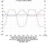
Results measured were for tails of resistance, inductance, NFET & LM317 to Common. And all to a negative supply of 22.4V, attempting to pull the cathodes down farther. Some of the results are summarized in the spreadsheet.
The best results obtained were with the Hammond 5H choke returned to common.
The blue trace shows the cathodes are pulled down only to 13.58 Volts. But the positive going part gets way up to >46 Volts. The result is very unsymmetrical & causes much distortion in the output signal.
The measurement system showed 5 Watts ..... but 18% of that was harmonics. Something to think about.😀
The Wattmeter I used is a MetraHit 29S, measures volts, amps & phase to get real watts. The Spectrums, Etc by a PicoScope 12-bit (72db) virtual instrument, 10 MHz BW.🙂
Attachments

- Status
- Not open for further replies.
- Home
- Amplifiers
- Tubes / Valves
- Idea for a 2 tube 6080 PP amp.