@ sebbyp,
would you please confirm that at your current setup / pictured you are doing without Fifo Pi
ESS Controller Is connected to ES9038Q2M DAC Hat ?
would you please confirm that at your current setup / pictured you are doing without Fifo Pi
ESS Controller Is connected to ES9038Q2M DAC Hat ?
Nice work sebbyp. Now you just have to make it look good 😉
Thanks Nickmac, planning chassis now 🙂
@ sebbyp,
would you please confirm that at your current setup / pictured you are doing without Fifo Pi
ESS Controller Is connected to ES9038Q2M DAC Hat ?
No, I use fifopi. Here is hopefully a higher resolution image.

thank you
Is It possible to use es9038Q2M Dac Hat with only JLSounds I2S over usb device without fifo pi
Is It possible to use es9038Q2M Dac Hat with only JLSounds I2S over usb device without fifo pi
Yes. If non sync mode is required, you just plug the 6 pins directly into the dac GPIO. I did this with the FIFO prior to implementing the reciever pi, which by the way is completely transparent and took nothing away from the SQ.
If you want sync mode, you need to ensure the USB board is in master mode, requiring to close a jumper on the back. Then you’ll need to take the Master Clock into the U.fl input on the dac board.
If you want sync mode, you need to ensure the USB board is in master mode, requiring to close a jumper on the back. Then you’ll need to take the Master Clock into the U.fl input on the dac board.
thank you for answer
As everyone prefer sync mode I will have to try It,
that way I put ES9038Q2M Into sync mode using ESS controller, use JLSounds 6 pins output connector Into dac GPIO except that MCL pin goes Into U. fl. Input on dac pcb
Is that correct
As everyone prefer sync mode I will have to try It,
that way I put ES9038Q2M Into sync mode using ESS controller, use JLSounds 6 pins output connector Into dac GPIO except that MCL pin goes Into U. fl. Input on dac pcb
Is that correct
Interesting piece on the imd hump in sabre chips.
How to Fix ESS Hump on SGD1 and LA-QXD1 | Audio Science Review (ASR) Forum
How to Fix ESS Hump on SGD1 and LA-QXD1 | Audio Science Review (ASR) Forum
Good to read up on your build sebby.
Have a few more hours on mine now and with the opa1612 still in place it is sounding very good. Haven't yet tried the 5532 back since adding in fifo ultimate.
I have just sourced a number of 0.22F 5v Cooper Bussman supercaps. I shall try adding some here and there.....maybe parallel 3 or 4 if I have the room.
Simon....thanks again...shall be in touch.
My current dac 3v3 rails are each on an LT1963. Do you think adding the supercaps after the regs before the dac will be ok? Regarding current on charging the caps?
My current dac 3v3 rails are each on an LT1963. Do you think adding the supercaps after the regs before the dac will be ok? Regarding current on charging the caps?
I use Ian's LT3042 boards, and the 3042's would have likely gone into thermal shutdown if I did nothing.
I had some little heatsinks I stuck on top of them from way back.
if you get a set of stick on pi heatsinks, the little ones should work. I put the corner of the heatsink on the 3042, taking care to keep the heatsink flat on the 3042.
Then I had a pc fan blowing on the heatsink when I charged the caps, to keep the temps down. Once charged, I never use a fan. I tried without the fan but stopped at around 85C because I was a long way from being done. With a fan, temps were always less than 50C on the heatsink.
Randy
Interesting piece on the imd hump in sabre chips.
How to Fix ESS Hump on SGD1 and LA-QXD1 | Audio Science Review (ASR) Forum
A really good find, has anyone tried to measure to see how significant the hump is with Ian's gear?
Also, I too would be interested to know the noise measurements of the hybrid supply. Unfortunately, I do not have the tools here.
A quick question, I use two master clock outputs from the Fifopi. Is there any way I can make the second one a pin output rather than U.fl?
A really good find...
Its hard to say what causes a hump exactly. Don't know if ESS knows. Some time ago they sent Scott Wurcer some private correspondence showing a time domain distortion magnifier view (distortion residual as seen in time rather than on an FFT) with a dac playing a -60dB sine wave. The trace showed what clearly looks like a type very strange and somewhat random crossover distortion-looking waveform, where sometimes the crossover transient was missing and sometimes inverted from what it should have been if it were actual crossover distortion. Obviously, it was some semi-random artifact being produced inside the dac chip.
Since that was found in a chip earlier than an ES9038 of any type don't know if its still an issue. If it is an issue, ESS just keeps it secret like they do everything else. My approach at this time is to forget ESS and move on to AKM AK4499. That's where the future of better sounding audio is going for now.
I definitely have my fingers crossed that Ian will design a dac board with the AK4499 that takes advantage of his existing eco-system.
I also hope is battery board V3. will be easier to implement hybrid rails.
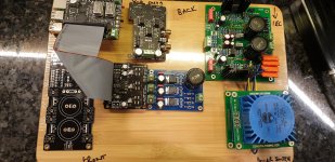
Layout proprosal
I am building a streamer for my brother and have all the bits to make a start. Having made a nice sounding one for myself without trying anything 'radical' I thought I could maybe employ some of the knowledge I have learned from this thread and make an improved version.
What do we think of the layout?
I shall need a longer u.fl cable for MCLK, maybe the 110mm long one that RS sells. Is this length ok regards interference? Maybe I try to shield it.i would likely use copper tape on the gpio extension cable.
Studer 900 powers IV std from it's own trafo. I have a Salas ubib 1.3 to build at some point but the 900 does a good job for the cost.
L adapter probably alone powers Rpi from one winding.
For the dac 3x 3v3 from ebay lt1963 from other winding. I use this supply on mine. Have fitted 0.33F button Panasonics to the 3 rails of the dac. Let's see how the regs deal with that!
Considered a single Studer900 for AVCC as ESS recommends an opamp buffered supply here. The Studer900 is such a device? It has opamp TL072. Not sure it will go down to 3v3. Maybe use at 5v and then reg down to 3v3 with Ian's 3042 3pin reg board.
Need another 3v3 for Fifo and a 5v for Recieverpi.
Maybe tap off the L adaptor....or I have some XRK cap mx psu boards and triple lt1963 boards I could use. Maybe another trafo for these
I have the ess controller extension kit
Considering building 'walls'from pcb to shield trafos and psus.
Will use those 40p cables to extend to the IV std from dac. Will be XLR output.
Generally I just wanted to make sure there is nothing inherently wrong with my proposal. My streamer is quite tightly packed in on a smaller chassis than this and I seem to suffer no I'll effects.
Thanks
Attachments
Or I ditch the Rpi and use a Google chromecast as the source into Ian's RecieverPi.
I also have a couple of Shield pi to use
I also have a couple of Shield pi to use
A great brother and looks great.
A couple of thoughts:
1) I would try and keep the u.fl cable under 10cm. I am planning using copper tape for my u.fl and I2s cables. If I get there first, I will let you know if I experience an improvement in SQ.
2) I know there are some posts that talk about using GPIO extenders either via cables between the FifoPI or pins cable extenders from dac to op-amp output stage. To reduce RFI etc. Controversial but IME, it has reduced the SQ by extending the distance for the signal to travel. I tried various cables from Amazon, Adafruit etc with the same result.
I would experiment with using extenders. If you prefer a single stack, it would provide a lot more space for the ultrabib, which could then be closer to the transformer.
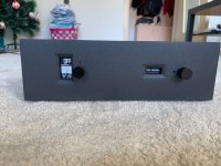
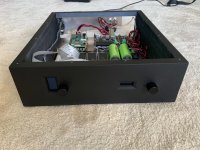
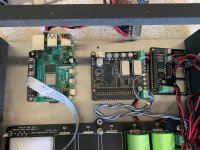
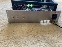
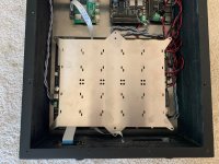
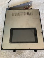
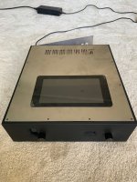
I'm still at the middle of building my player but I think now is the moment to share my progress and to ask for advice. I made a plywood box, top, bottom and back panels are stainless steel. Metal parts arent painted yet.
Bottom panel is designed to have all options of assembling RPI, FiFo and dac - one stack, one by one or FiFo and dac stacked next to RPI.
My target is the highest possible sound quality. So I'll be very thankfull for your appinion how to acheev it!
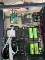
1. Waht is the best way to connect all parts together? My plan is to install all parts separated. To connect FiFo ULF I2S outputs to dac by Ians RPI I2S adapter. The same way RPI FiFo non isolated part or ribbon cable.
Furter upgrade will be to install on top of RPI Ian's UcConditioner.
2. What clocks to use for best SQ?
3. Supper cap - bigger capacity or lower ESR?
4. Does anyone knows where to buy panel mounted micro sd card adapter (some kinde sd card extender)? It will be wery useful to have accesible microSD card on back panel.
And finally one for Ian. My RPI is constantly powered on - so ESS controller too. Issue is that display is always on and bigger problem is when powered on dac for second time the ess not initialize dac chips. Is it posible to make firmare upgrade with screensaver and if there is not imput signal ess to check dac chip is still alive?
Bottom panel is designed to have all options of assembling RPI, FiFo and dac - one stack, one by one or FiFo and dac stacked next to RPI.
My target is the highest possible sound quality. So I'll be very thankfull for your appinion how to acheev it!
1. Waht is the best way to connect all parts together? My plan is to install all parts separated. To connect FiFo ULF I2S outputs to dac by Ians RPI I2S adapter. The same way RPI FiFo non isolated part or ribbon cable.
Furter upgrade will be to install on top of RPI Ian's UcConditioner.
2. What clocks to use for best SQ?
3. Supper cap - bigger capacity or lower ESR?
4. Does anyone knows where to buy panel mounted micro sd card adapter (some kinde sd card extender)? It will be wery useful to have accesible microSD card on back panel.
And finally one for Ian. My RPI is constantly powered on - so ESS controller too. Issue is that display is always on and bigger problem is when powered on dac for second time the ess not initialize dac chips. Is it posible to make firmare upgrade with screensaver and if there is not imput signal ess to check dac chip is still alive?
Attachments
Last edited:
- Home
- Source & Line
- PC Based
- IanCanada's Latest RPi GB Goodies Impressions... and your tweaks, mods and hints...