darian
as what I could see, your circuit follows Steve's Posted schematic well.
in Post #114
Schematic:
http://www.diyaudio.com/forums/attachment.php?s=&postid=1650044&stamp=1225835894
as what I could see, your circuit follows Steve's Posted schematic well.
in Post #114
Schematic:
http://www.diyaudio.com/forums/attachment.php?s=&postid=1650044&stamp=1225835894
Well, there is also a discrepancy in the value of the resistor bypassing one diode, once 180 and once 10000 in another schematic. The 10k value makes more sense to me, actually remove it makes more sense to me, anyway.
To Lineup, as I said, the only way I found to understand this emittor to collector stuff is to view the whole transistor as a resistor since it's emittor to collector voltage is always less than a diode threshold. And in this case, in the textbooks this saturated transistor behaves like a resistor of small value. So my intuition was to imagine this value would dynamically change with the input voltage and that would be the "trick" everyone was looking for in this circuit. But apparentely that's not it and the whole stuff behaves weirdly.
I really would like to understand this circuit from Mr Dunlap, would there be a schematic error to correct. We didn't go deep in the explaination despite 8 pages of chatting... I'm just curious you know. It really left me on a cliffhanger, and Dx was making such a big fuss around it at first.
Regards
Darian,
I know very little about amp designing but I know about reading schematic and I can say your schematic is wrong.
Just to remember there is a node only where there is a dot.
For example in your schematic C4 is linked to Q22 Q21 Q13 and Q14 which is not the case at all in the original schematic where C3 (equivalent to your C4) is only linked with the node where the 47k the diode are linked.
I think you should redraw completely your schematic and pay attention to those nodes.
The 470uF are also missing
And in this case, in the textbooks this
saturated transistor behaves like a resistor of small value.
Thanks for this Information
I did not know this.
Can help to understand the idea with this configuration.
saturated transistor behaves like a resistor of small value.
Thanks for this Information
I did not know this.
Can help to understand the idea with this configuration.
Cedus & Darian,
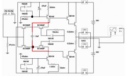
See DX reworked schematic:The 1uF cap Is in the wrong position. It should connect between the bases of the Darlington output pair. R4 should be a 10K variable resistor. Start with it set to lowest value and increase to set bias.
Attachments
Is this seventh harmonic audible?
It seems will be very slow level..do this disturbs sonics?
Interesting what halojoy said...and other friend said will be annoying into the long term ....interesting.
Into Radio Frequency, and i used to adjust into the spectrum analizer, the 7 harmonic used to be very small level..not really bothering the transmission or producing interferences or strange side bands.
regards,
Carlos
Thanks Jkeny for this precision. I'm afraid it's not solving the problem. This 1u cap doesn't really participate in the understanding of this circuit anyway, actually in simulation its influence is so minimal it could be omitted. And for the variable resistor, for any value the diodes are off and stay like that so I still wonder. To Lineup, you can see on the graph I posted that for low Vce voltage the relation between Vce and Id is a line and this relation is kept for more Id current if the Ib is higher then. But under 10mA of Id, that line is pretty much independant of Ib as long as Ib does exist of course. Thanks for your help guys, I really appreciate.
Regards
Regards
Attachments
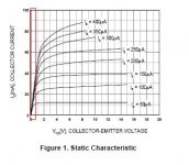
look up the Vsat curves.
They should confirm the voltages around those two saturated transistors.
Now look at the voltage from base to base of those same two transistors. The maximum current trying to flow through 180r+one diode can only be in the uA range.
A saturated transistor cannot operate with such a tiny base current.
gains of 5 to 20 are much more common for a saturated transistor. If uA flows in the base then the collector current is of the order of 10s of uA.
There is something wrong with the original schematic.
Hello again,
Andrew, the current in the base is about 40uA according to simulation. It's not much actually, but the state of the base is less important in this portion of the curve as you can see as long as we don't go past 10mA. There is no transistor effect working in this saturated mode so that's why the base current is less important. There is more or less no more "gain" notion on this portion of the graph. Anyway, the cutoff currents are more in the nA I think. Anyway, it's not enough to turn on the diodes.
I agree, there is something wrong with the schematic...
Regards
I agree, there is something wrong with the schematic...
The schematic as posted by jkeny appears to be correct.
The schematic as posted by jkeny appears to be correct.
I agree, there is something wrong with the schematic...
The schematic as posted by jkeny appears to be correct.
Here is the rest of what I was trying to say before the cat walked across the keyboard.
If you feel that the diodes are not conducting, try the sim without them. They are conducting. The exact amount will vary with the gain of the transistors, 80uA with the ones I use (2SA1306A and 2SC3298B). You will (or should) see that there is also an AC component - check any point between the transistor bases - that is identical to the output.
The transistors are run in the near pinch off mode on purpose and this is why the circuit works.
As for simulating the circuit, I tried three programs that would not show the circuit to work. I knew it worked because I had already built about 200 amps. The fourth and final sim program I tried was ICAP/4 by intusoft. This is not a free or even inexpensive program but it gave me results that matched what I was measuring in the actual circuit so I stayed with it.
Seventh harmonic? How interesting.
Steve
Hello Steve,
Thank you for your answer. I get the idea of the diodes turning on more to up the bias. This is just not working in Microsim, but I was using 1N4148 diodes so... I'll try with other ones I guess. For sure 80uA are not enough to bias these ones in MicroCap. Maybe MicroCap is not good enough, I don't know. I just know it's anyway way better than LTspice I used before!
Thanks anyway, I'll tell you how it went!
Hey, here's an idea - why doesn't somebody build it & report back- after all there seemed to be a lot of impatience on this thread before Steve kindly published his schematic - has all that impatience dissipated or could it be channeled into a build, perhaps?
Hello again,
Thanks Mr Dunlap for your comment, it works better in Micro-cap with the transistor models you used and not the BC kind. Less Beta leads to more current in the polarisation diodes and better "turning on". Now they are close from the elbow part of the exponential curve and the dynamic bias is more effective. Nevertheless it is still obvious that there is a full lot of odd order harmonic in simulation, probably from residual crossover distortion artifacts, so I'm sure there is room for closer matching of devices to make them work as intended. And still, I get good results with only 22 Ohms resistors in place of the cascode transistors even with only tenth of uA bias at the output. So maybe they really work in the saturated mode like books say? Who knows... But for sure it's a little better with the modulation of the diodes which is showing the lasting Ib influence even in saturated mode (obviously it's way more influencial for high Ib, above 100uA). But as I said, it's very subtle and depending on how close to the elbows of the exponential curves you are.
To Cedus, I am happy to see a french person on this forum! The C4 cap is not really that critical to the design but I agree I made a mistake. The 470uF caps are totally not required in the simulation and I omitted them on purpose because my power supply is considered perfect here so no ripples to smooth...
Regards
You are correct about the 470uF caps. No ripple in sims. A
A resistor may replace the diodes, either one or both. The diodes serve dual purposes. One is to set the bias voltage high enough so that I can use the parallel resistor across the one to trim the bias to the desired level. I set it to give minimum distortion at a desired output power. This may be selected to be the rated power or a preferred listing level, say 10 watts. Either way the distortion should be below .01% at any frequency from 20 to 20K and any power up to rated. I have measured .005% THD+noise on one amp at 400W at 20K Hz. This is typical of that model.
The other reason I use diodes is so I may place them on the heat sink to provide thermal tracking.
Steve
planet10 said:
Technics built a series of amps called New ClassA using this kind of trick. They are quite decent sounding...
dave
The trick with getting a large # of those Technics class AA amps up and running..is that they pulled a sneaky trick: The bulb that lights up the Class AA logo on the front panel is part of the protection circuit,and the amps will not go out of protect mode unless that bulb is working properly.
Quad SPST Analog Switch
Hi
I am sorry to intrude but I also found a very special amp... After opening the pre amp to recap, I found that the output stage consists in a opamp followed by a SPST (DG308 16 pin integrated).
I can not imagine what is the purpose of the switch (maybe to cause a time lag between power on and hearing a thump on the speakers).
I would like your oppinion on this chip...does it obviate the need for output caps ? (I can not find any in the preamp)
Does this chip add distortion or colorations to the sound ?
Should I remove it ?
Hope some one can help me.
Regards
Ricardo
Hello,
I think a cap is rarely needed at the output of the preamp for a good reason : there is a cap at the input of the power amp in 99,99% of the time! So you can check if there is a cap at your power amp input and get rid of the weekest one. And for the question if the switch does alter the sound, I would say probably a little since it's not a mechanical switch but a fet and they are never perfectely purely resistive (as the datasheet confirms it).
Regards
Thank you darian.
Just by reading the schematic, I believe there is no input cap on the power amp.... I must open it to check.
Can you imagine why this switch is there (between opamp and output ?)
Ricardo
Just by reading the schematic, I believe there is no input cap on the power amp.... I must open it to check.
Can you imagine why this switch is there (between opamp and output ?)
Ricardo
Probably as you said, to delay the transmission of signal at power on to let the circuitry time to settle, and probably also a mute function or so. Nothing too interesting to my taste anyway. You can try to shortcut it with a piece of wire and see how it sounds at power on, no need to desolder it.
Regards
Regards
- Status
- Not open for further replies.
- Home
- Amplifiers
- Solid State
- I have found a special amplifier, am trying to contact the designer