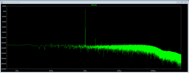
I am not sure what I am doing wrong. I think I have something set wrong. I am getting a flat line in the FFT Plot.
To get a good FFT you need to do a couple of things:
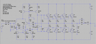
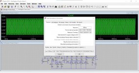
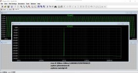
1/ Run the sim for a good length of time and set it to ignore the very start of the run. I'm using 600ms and 400ms here, see attached image.
It will take a couple of minutes to run. The FFT is only of use on a sine input. Make sure you have the timestep parameters set correctly... which they are for 1kHz in these sims.
2/ Take out time constants such as the input coupling cap and the feedback return cap. The easiest way is to just make them very big such as 1 Farad. When entering this value just enter '1''. Curiously (I think this is a bug but Mike Englehardt doesn't 😉) 1F (and F is the unit for Farad) gives a value of 1 femtofarad.
Sometimes a sim won't converge or run when you do this and you find that 999,999uF might run while 1000,000uF won't.
I notice you have linked out the 470uF feedback cap in your sim. That will give a horrible DC offset as the input bias currents are now very unmatched.
Attachments


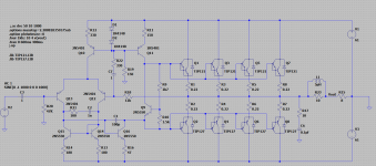
Corrected.
Curious. I have seen the Zobel network on either side and sometimes both sides of the output inductor. I am not sure what good it would do on the leading side since they are specifically to deal with the inductance of the speaker.
Am I correct in thinking that if you are wanting to tune the amp to cut off at a particular frequency you can adjust the values to tune the Network. Say for example you are building a Bi-Amp System you would have different values for the Bass than you would for the Mids and Tweeters.
Attachments
Member
Joined 2009
Paid Member
Just an fyi - I have had good success with power Darlington output devices, low distortion and good sound. My approach was to re-engineer my home theatre receiver amplifiers. I've done it twice now, to two different generational models. I also have some of the power devices left over from the first project, was thinking of building something else one day.
TGM6 - modified Pioneer HT amplifier
TGM6 - modified Pioneer HT amplifier
Corrected.
Curious. I have seen the Zobel network on either side and sometimes both sides of the output inductor. I am not sure what good it would do on the leading side since they are specifically to deal with the inductance of the speaker.
Am I correct in thinking that if you are wanting to tune the amp to cut off at a particular frequency you can adjust the values to tune the Network. Say for example you are building a Bi-Amp System you would have different values for the Bass than you would for the Mids and Tweeters.
The Zobel network attempts to maintain stability when the amplifier is faced with an inductive load. It also terminates the amplifier into a defined load at high and very high frequency and in fact some amplifiers are inherently unstable without such a network, even with no load connected.
The series inductor counters the effect of purely capacitive loading, without this many amplifiers would self destruct if a purely capacitive load was connected across the output.
If a design incorporates a second network on the output side of the coil then this creates a PI filter which can be useful for preventing RF entering into the amplifiers output node. They are not that common in my experience though.
You can not tune the amplifiers response with any of these circuits and variations, that must be done either by selective feedback network or by having some filter at the input. The main purpose of these networks is to try and make the amplifier see a 'resistive' type load no matter what the user hangs on the end of the terminals.
Some amplifiers do incorporate the bass and treble controls within the power amp feedback loop.
Thanks Mooly.
Question on calculating the maxstep time.
My calculations gave me 600ms /262144 = 2.288818359375uS or should I be using 200ms/262144 =0.762939453125uS
Or something Else.
Question on calculating the maxstep time.
My calculations gave me 600ms /262144 = 2.288818359375uS or should I be using 200ms/262144 =0.762939453125uS
Or something Else.
Does anyone have an asc of a well built amp. It would be good for me to use to compare the results I am getting. I see issues but I am not sure if it is the way I am setting up lt spice or if it is the design.
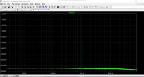
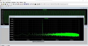
I have noise on the FFT what I don't understand is why the noise is on the Vout and the Vin also.
Here is what I have so far.
I have noise on the FFT what I don't understand is why the noise is on the Vout and the Vin also.
Here is what I have so far.
Attachments
Let me re-hash it with a one off example using really weird values.
We will first of all take those two electrolytics out of the sim by making them 1 Farad.
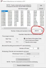
Let us simulate an FFT for 697 Hz input signal. To do this we need to work backwards from the FFT screen, the screen that offers a choice of sample points (image 1). Have a look at the options and decide... experiment. Less is sometimes better for clarity in some audio sims and the big difference you will see is in the frequency scale at the bottom.
So I'm going to use 65536 today. You can enter this when you get to run the FFT, you just need to decide first what you will use for the calculation. Once you have calculated this you will actually find the calculated timestep works OK for other sampling values as well.
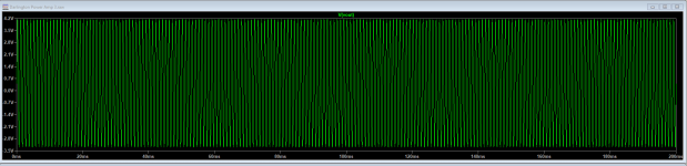
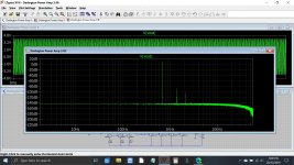
Lets put that into a sim and see what happens. We need to look at many cycles of signal to get a detailed trace and so we shall run the sim for 400 cycles of clean data. That means we meed to run for a total time exceeding that and to just collect that last 400 cycles of the run.
I'm using Windows on screen calculator for all this because you can just copy and paste the raw results.
1/ Calculate the period of 1 cycle. This 1/F which is for 697 Hz:
0.00143472022955523672883787661406 seconds.
2/ Calculate how long our chosen 400 cycles will run for. This is the above multiplied by 400:
0.5738880918220946915351506456241 seconds.
3/ Divide our chosen sampling point setting (65536) into the above figure. This is our timestep to enter in the sim:
8.7568373385939741750358680057389e-6
4/ Calculate the time to start saving data. We know the sim must run for at least 0.58 seconds to cover our wanted 400 cycles and so lets pick 800ms as a total run time. We subtract (exactly) the result in step 2 from 0.8 seconds giving:
0.2261119081779053084648493543759
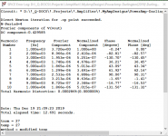
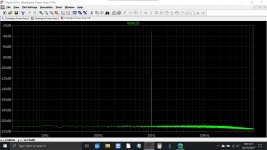
Run the sim and the FFT is now as good as it gets even though we used whacky values.
We will first of all take those two electrolytics out of the sim by making them 1 Farad.
Let us simulate an FFT for 697 Hz input signal. To do this we need to work backwards from the FFT screen, the screen that offers a choice of sample points (image 1). Have a look at the options and decide... experiment. Less is sometimes better for clarity in some audio sims and the big difference you will see is in the frequency scale at the bottom.
So I'm going to use 65536 today. You can enter this when you get to run the FFT, you just need to decide first what you will use for the calculation. Once you have calculated this you will actually find the calculated timestep works OK for other sampling values as well.
Lets put that into a sim and see what happens. We need to look at many cycles of signal to get a detailed trace and so we shall run the sim for 400 cycles of clean data. That means we meed to run for a total time exceeding that and to just collect that last 400 cycles of the run.
I'm using Windows on screen calculator for all this because you can just copy and paste the raw results.
1/ Calculate the period of 1 cycle. This 1/F which is for 697 Hz:
0.00143472022955523672883787661406 seconds.
2/ Calculate how long our chosen 400 cycles will run for. This is the above multiplied by 400:
0.5738880918220946915351506456241 seconds.
3/ Divide our chosen sampling point setting (65536) into the above figure. This is our timestep to enter in the sim:
8.7568373385939741750358680057389e-6
4/ Calculate the time to start saving data. We know the sim must run for at least 0.58 seconds to cover our wanted 400 cycles and so lets pick 800ms as a total run time. We subtract (exactly) the result in step 2 from 0.8 seconds giving:
0.2261119081779053084648493543759
Run the sim and the FFT is now as good as it gets even though we used whacky values.
Attachments
Noise...
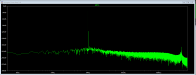
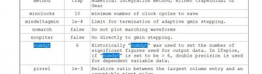
This shows the input noise using my method (back to 1Khz now) and then using another trick to increase the mathematical precision of LT which didn't seem to make much difference here.
This shows the input noise using my method (back to 1Khz now) and then using another trick to increase the mathematical precision of LT which didn't seem to make much difference here.
Attachments
- Home
- Amplifiers
- Solid State
- I have about 30 Darlington Pairs