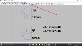
Can I get the LTSpice models for the power transistors from you, please?
The models are actually some of Mike Englehardt's and are buried in an example sim included with LT.
Try this. The .asc called Darlington Workspace should open to a workable file. Use the copy function to add more to your circuit as required.
Attachments
Try this. The .asc called Darlington Workspace should open to a workable file. Use the copy function to add more to your circuit as required.
Thank you.
I don't have LT Spice models for them. I am still trying to re-learn with LTSpice. So far I have not been able to get it to open my exported schematic.
If you download Mooly's sim, it works except for the missing models for the TIP series outputs.
Also, play with some of the examples included in LTSpice... sometimes it's very easy, but some of it is just a royal pain in the patookis.
same transistors family but different voltage rating.Thanks 🙂 Are those identical to the TIP121/127 models?
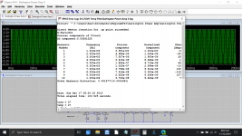
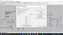
I did some tinkering and I think I have usable data but I am not sure. On the ltspice schematic. I adjusted the Value of R18 to get maximum gain with the least amount of impact on the frequency range and distortion.
Not sure how accurate since the library is not for the actual outputs I am using. Also really new to ltSpice.So I am not totally sure I am using it correctly. I think I learned on a different program 3 Decades ago.
I used Mooly's "Installing and using LTspice IV (now including LTXVII). From beginner to advanced" and it was very helpful. Not quite as good as hands on but darn close.
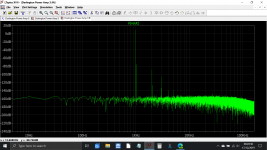
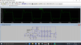
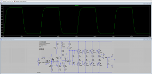
Not sure what to think about the ringing on the last picture. It is outside of the audio frequency but will it be an issue?
Not sure how accurate since the library is not for the actual outputs I am using. Also really new to ltSpice.So I am not totally sure I am using it correctly. I think I learned on a different program 3 Decades ago.
I used Mooly's "Installing and using LTspice IV (now including LTXVII). From beginner to advanced" and it was very helpful. Not quite as good as hands on but darn close.
Not sure what to think about the ringing on the last picture. It is outside of the audio frequency but will it be an issue?
Attachments
Last edited:
I did some tinkering and I think I have usable data but I am not sure. On the ltspice schematic. I adjusted the Value of R18 to get maximum gain with the least amount of impact on the frequency range and distortion.
Actually you don't want maximum gain. What you want is for the amplifier to reach something like 99% power with a standard line input level, either pro or consumer (PLL or CLL).
The levels are defined... HERE
Not sure what to think about the ringing on the last picture. It is outside of the audio frequency but will it be an issue?
Yes. It can be an issue since it's a pre-cursor for oscillation.
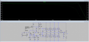
This is starting from the original simulation:
First image is just the original sim and it is a little nervous (and whatever you do with a real build, you must add a little series inductance at the output for stability into real loads).
Second image shows what I altered. Input filter added as well.
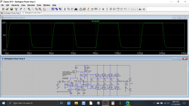
Third image shows squarewave setting for voltage source to give 25kHz signal. Set the sim to run for 160uS to display four cycles.
Fourth image shows new result of squarewave test.
Fifth image shows the overall response and gain.
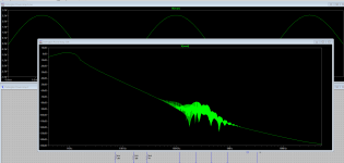
Sixth image is an FFT plot at 1 watt/8ohm. It is so good because the bias current of the four pairs of outputs means it is in class A at this point.
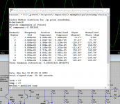
Seventh image is the headline distortion figure.
First image is just the original sim and it is a little nervous (and whatever you do with a real build, you must add a little series inductance at the output for stability into real loads).
Second image shows what I altered. Input filter added as well.
Third image shows squarewave setting for voltage source to give 25kHz signal. Set the sim to run for 160uS to display four cycles.
Fourth image shows new result of squarewave test.
Fifth image shows the overall response and gain.
Sixth image is an FFT plot at 1 watt/8ohm. It is so good because the bias current of the four pairs of outputs means it is in class A at this point.
Seventh image is the headline distortion figure.
Attachments


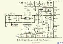
Nice to see you guys are re-inventing the wheel, so to speak. Did you look at this design that Bob Cordell presented at BAF2019? Many ways to make an amplifier, but how complicated does one need to get to achieve the goals. This is a working and tested design.
Attachments
Last edited:
Nice to see you guys are re-inventing the wheel, so to speak. Did you look at this design that Bob Cordell presented at BAF2019? Many ways to make an amplifier, but how complicated does one need to get to achieve the goals. This is a working and tested design.
The OP has been quite clear in saying that he wants the exercise in designing his own amplifier.
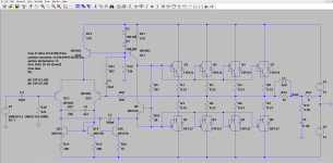
I stripped a whole bunch of old Sony amps and I would like to re-purpose the output transistors. I looked at the schematic for one and it was a class h amplifier using a 2 pairs of MN2488 and MP1620 Darlington Transistors. I have attached the schematic I came up with from it. I am new to building (Kind of anyway) I usually just modify existing amps to put out more power.
Can anyone that has built a few look this over and tell me if there is anything I have totally messed up or can do to improve it before I get the boards made?
Also
I would really like to see a schematic of a class ab amplifier and have someone explain to me what every part does or point me to a book that goes into more detail that just This is a long tail pair, This is a driver stage, ETC ETC ETC.
I posted a design in which some one has explained in a whole chapter of a book, dedicated to audio power amp design, then presented it to the DIYAudio community, there is a youtube video as well, explaining exactly what every component does.
YouTube
the book
http://www.cordellaudio.com/book/Book2_Preface.pdf
https://www.amazon.ca/Designing-Audio-Power-Amplifiers-Cordell/dp/1138555444
I think I was quite clear in my response as to a book that does what was being asked and a design that meets the requirement of the OP.
@kilgorq, does this answer your original posting? if you want the pcb for the above amplifier PM me. If you post your layout I can look it over.
Last edited:
I watched this video. Honestly not sure where it described every part. The circuit topology is interesting but it was more like a 100 foot view of it. I have read about 100 Pages of the book and am still trying to get back to it. Kids are grown up but unable to do anything without someone holding there hands. A Remote Island sounds good but being a father never ends.
I am not trying to re-invent the wheel. I have decent grasp on the subject. I understand how the stages work together and what they do. I could just order an amp kit and assemble it and call that DIY. Been there done that. But that is not what I am after. I want to learn more about the subject matter. I want to get good at using the simulator and understand why I get the results that I do. I guess maybe my question was not detailed enough. For example I want to understand why amp A Sounds better than amp B. What is different in the circuit. Or how changing the value of a resistor changes the performance of an amp and more importantly why!
I have taken something new away from the help I have received so far an it is very much appreciated.
In response to last post Mooly showed me something I completely missed about looking at the square wave. And Douglas confirmed my suspicions on the ringing I was seeing.
I need to find some time to look closer at what Mooly Posted. It is interesting. I need to put it in the simulator and see how it works. Maybe play with the values some to see how they effect the overall circuit and may have an ah-ha moment where I get some more clarity.
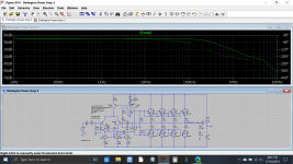
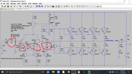
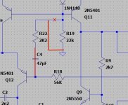
Ok, lets address something I've been seeing all the way through this design process...
Follow your feedback path through R18 ... then C4 ... into R22... and to the base of Q11 ... if you work out the effect of this chain you actually have positive feedback happening. It's not much, maybe 10% but it will be enough to cause some instability that might well become audible.
It needs to be redone as I've shown ... R18 to R22 to ground. This eliminates the positive feedback and your gain is then set by the ratio of R22 and R18 ... like in an opamp, which is basically what you are designing. R18 still needs a low value capacitor across it to limit gain at higher frequencies also to prevent oscillations.
Attachments
Last edited:
Sixth image is an FFT plot at 1 watt/8ohm. It is so good because the bias current of the four pairs of outputs means it is in class A at this point.
I am not sure what I am doing wrong. I think I have something set wrong. I am getting a flat line in the FFT Plot.
Update.
Can you upload the .asc file for this, please...
It turns out you may have to keep C4...
Last edited:
- Home
- Amplifiers
- Solid State
- I have about 30 Darlington Pairs