Obviously, multiple amps of current are not going through those 47k resistors! (2.5 Amps RMS, for 50 Watts RMS into 8 Ohms, for example, would cause a 47k resistor to dissipate (2.5)²(47000) = 293750 Watts RMS, and would require 117500 Volts RMS or 166170 Volts peak across the resistor!)
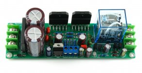
If you look next to (i.e. before) the 47K resistors, there are labels, "IN1" and "IN2". Those go to the output, way on the right, through the speaker protection relay.
If you look next to (i.e. before) the 47K resistors, there are labels, "IN1" and "IN2". Those go to the output, way on the right, through the speaker protection relay.
Last edited:
Thanks Gootee!! Those labels were near invisible. 🙂
Err..still, I want to understand what function are the transistors doing here. Looker harder, I think they are basically triggering/driving the protection relay?
Correct me if I'm wrong.
Thanks,
Aashish
Err..still, I want to understand what function are the transistors doing here. Looker harder, I think they are basically triggering/driving the protection relay?
Correct me if I'm wrong.
Thanks,
Aashish
Indeed, the entire transistor circuit appears to be the add-on speaker-protection board that was mentioned in the thread.
Obviously, multiple amps of current are not going through those 47k resistors! (2.5 Amps RMS, for 50 Watts RMS into 8 Ohms, for example, would cause a 47k resistor to dissipate (2.5)²(47000) = 293750 Watts RMS, and would require 117500 Volts RMS or 166170 Volts peak across the resistor!)
If you look next to (i.e. before) the 47K resistors, there are labels, "IN1" and "IN2". Those go to the output, way on the right, through the speaker protection relay.
47K Resistance at the ends of the current calculation
35V(OUT VOLTAGE<35V)/47000=0.74MA
It is used, to avoid error protection circuit operation, dc protection.
Recently, I buy from international suppliers to the new quality goods LM3875TF.
It is very convenient to install. Really comfortable effect.
I think LM3875TF better than LM4780 or LM3886.
The influence of the circuit may be 47 lab. May be lower SR speed, more pleasant voice.
Last edited:
I bought one of these boards a few weeks ago and really like the design. Having the speaker protect and power supply on the same board makes it super easy to hook up and is very compact so it will fit inside some pretty small cases.
I bought the board for just under $20 with shipping. I had some had some chips on hand that I got for free as samples and pulled a transformer out of a junk receiver that I pulled out of the trash. I re used the heat sink and jacks from the junk receiver too so in the end I have very little stuck into this nice sounding amplifier.
What I really like is these amps are sold as a kit with out the main chips so you can buy your own and don't have to worry about getting a cheap clone. You can also choose to up grade any of the parts since nothing is soldered up. Heck, $20.00 is almost cheap enough to buy this for just the circuit board and buy all of your own parts.
Dale P.
ljm_ljm.
I am no expert but the 2200 uf capacitors seem small for this much power. Please share your reasoning for sizing these capacitors. Also what AC transformer spec would you recommend?
I am no expert but the 2200 uf capacitors seem small for this much power. Please share your reasoning for sizing these capacitors. Also what AC transformer spec would you recommend?
ljm_ljm.
I am no expert but the 2200 uf capacitors seem small for this much power. Please share your reasoning for sizing these capacitors.
Actually, 2200 uF is fine for on board caps if you use a separate board for the rectifier and some bigger caps. 😉
This approach has a couple of advantages too. It removes heat away from the board (both the caps and rectifier generate heat) and it puts a faster capacitor (the 2200 uF) closer to the amp. It also allows you to use bigger ripple caps (bigger both in value and in physical size).
Parallel caps will have lower esr than a single cap too, which is an important parameter to optimize for this application.
Now, I designed "THE GAINCUBE"
Since the first time I saw this little marvel, I thought that it deserves a nice (and different) enclosure.
And this is the result, "THE GAINCUBE".
All made of aluminum 6061, brushed (in process), and anodized (soon).
It uses a 200 VA Antek 28-0-28 transformer, and a 28 step DACT potentiometer.
That's all.
Photos:
Actually, 2200 uF is fine for on board caps if you use a separate board for the rectifier and some bigger caps. 😉
This approach has a couple of advantages too. It removes heat away from the board (both the caps and rectifier generate heat) and it puts a faster capacitor (the 2200 uF) closer to the amp. It also allows you to use bigger ripple caps (bigger both in value and in physical size).
Parallel caps will have lower esr than a single cap too, which is an important parameter to optimize for this application.
May be a dumb question but how do you bypass the on board rectifier?
May be a dumb question but how do you bypass the on board rectifier?
Yank it out and hook up the power leads from the power supply board to the plus and minus holes for the rectifier.
Yank it out and hook up the power leads from the power supply board to the plus and minus holes for the rectifier.
Finished my build based on the ljm's PCB. I must say it sounds very nice.
Used an Antek 200VA transfermer with 25V secondaries.
By the way, in order to use an external power supply board you don't use the onboard rectifier and you need to jumper holes 1 and 3 for the rectifier and connect the +V power supply to pin 1. This powers the +V rail and the soft start circuit. Connect -V to hole 4 for the rectifier.
The thing that people say about the larger the better,ain't true and setting everyting parellel increase 0ffcourse resonance probs. I allways wondered why guys with subwoofers in their cars , use a couple of farad's. And i doubt if they get a right spectrum.Those sub
pwersupilies doesn't cost a thing .
pwersupilies doesn't cost a thing .
can someone help me on what value and where to put a gain/volume control potentiometer on this?
Thanks!!!
Thanks!!!
Not necessary to bypass the rectifier. Run the external DC source to the AC input. You loose a few diode forward voltage drops, minor loss, great convenience.
can someone help me on what value and where to put a gain/volume control potentiometer on this?
Thanks!!!
I usually put it after the Input, and i use 50K log potentiometer.
Hi Pemo,Since the first time I saw this little marvel, I thought that it deserves a nice (and different) enclosure.
And this is the result, "THE GAINCUBE".
All made of aluminum 6061, brushed (in process), and anodized (soon).
It uses a 200 VA Antek 28-0-28 transformer, and a 28 step DACT potentiometer.
That's all.
Photos:
View attachment 410905
View attachment 410906
View attachment 410907
View attachment 410908
View attachment 410909
View attachment 410910
Nice build ☺ how does it sound ?
Hi Pemo,
Nice build ☺ how does it sound ?
Oh, hello. Sorry for the delay answering (it's been several months).
This amp is a very, very, very good sounding machine. Very detailed. Clear highs, tight bass, marvelous mids.
My other amp is a LM3886. I can't tell which I like most.
RGDS,
PEMO
- Home
- Amplifiers
- Chip Amps
- I designed the GC LM3875