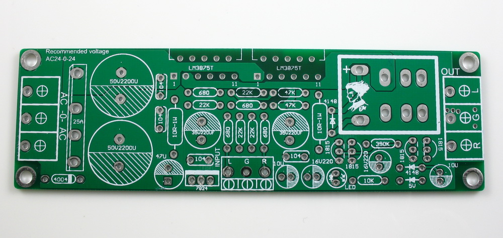
Just got my board, based on the info in this thread, should be a simple build. Board is of very nice quality.
One question: It seems there is a difference opinion on the need to remove/keep the bridge rectifier if inputting DC ...
Here:
Not necessary to bypass the rectifier. Run the external DC source to the AC input. You loose a few diode forward voltage drops, minor loss, great convenience.
and Here:
By the way, in order to use an external power supply board you don't use the onboard rectifier and you need to jumper holes 1 and 3 for the rectifier and connect the +V power supply to pin 1. This powers the +V rail and the soft start circuit. Connect -V to hole 4 for the rectifier.
Of course, both can be correct, any thoughts on a best practice?
Thanks;
Dave
Maybe the external DC can come from a stiffer supply with larger supply caps. But leave the supply caps on the board as it is.
The amp sounds very good but I felt it's a bit too sharp at times. I added the inductor (0.7uH) and 10 ohms parallel resistor in series with the speaker. On a quick listen I think it eliminates that occasional sizzle. Not sure if that's the mind playing tricks but I feel it sounds better.
The L/R is shown on the application note.
There is an option to short out the NFB decoupling cap. Didn't try it that way. Maybe I will. Should improve the bass . Will have to check how much the speaker offset voltage is. Right now it's below 1mV on both channels. Note that the input is dc coupled.
The circuit on page 1 does not show the dc decoupling cap in the NFB loop. I liked the board so much that I bought another one !
Last edited:
Thanks Ashok, looked at the application note, and sure enough, inductor and resistor right there before the speaker!
I have both the TDA7294 and LM3875 boards. As I said, initial comparison showed the LM3875 to sound a bit 'sizzly' at times and I felt that voice on peaks sounded 'noisy'...'shouty' , like it made me feel like turning down the volume . The TDA 7294 wasn't like that.
With the 0.7uH/10 ohm combination in series with the speaker this problem seems to have been solved. I didn't spend much time listening but the problem section of music didn't appear so bad. I'll do some critical listening later on.
The coil is a 0.9mm enamel wire wound 11 turns on a 9 mm former ( ball point pen casing !) . It's just about 10 mm long . I placed the 10 ohm 1 watt resistor inside the coil and soldered the coil leads to it.
Attachments
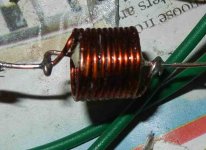
Just in case anyone wants to know how I actually wound the coil.
I took a ball pen casing ( 9mm dia) and removed it's end cap. Wrapped four layers of plastic sheet on it ( regular outer plastic wrapping from a box) . Then wound the coil on it and dropped instant glue on it. Held it for a short while till it set and then after it was fully set ( about 15 minutes) I slid it off the former. The plastic sheet sticks to it but can be easily removed. I had an enamel remover liquid which I used to remove the insulation. Easy but very corrosive liquid. I accidentally spilled a drop on my hand and it burned it though I washed it immediately. It now has a brown mark like a regular 'fire' burn ! If you use such a thing , be VERY careful. Safest is to just scrape off the insulation with a sharp knife!
I took a ball pen casing ( 9mm dia) and removed it's end cap. Wrapped four layers of plastic sheet on it ( regular outer plastic wrapping from a box) . Then wound the coil on it and dropped instant glue on it. Held it for a short while till it set and then after it was fully set ( about 15 minutes) I slid it off the former. The plastic sheet sticks to it but can be easily removed. I had an enamel remover liquid which I used to remove the insulation. Easy but very corrosive liquid. I accidentally spilled a drop on my hand and it burned it though I washed it immediately. It now has a brown mark like a regular 'fire' burn ! If you use such a thing , be VERY careful. Safest is to just scrape off the insulation with a sharp knife!
The output Zobel adds a load that the amplifier sees at high frequency.
This helps prevent the amplifier going towards a less stable operation.
Attach a reactive load and you force the amplifier into a less stable operation.
Before the amplifier oscillates it shows up low stability symptoms. One of these can be seen an a scope.
It is overshoot when presented with a fast signal. Difficult to see with a 10kHz sinewave. Use a 1kHz sqw and the overshoot shows clearly. If the overshoot tails off without ringing then the amplifier may just be stable enough to not sound bad when playing into a speaker.
If there is overshoot and prolonged ringing, then the amplifier will almost certainly sound bad. JLH had a procedure described in his build article of the 80W ClassAB amplifier, where he adjusts the overshoot to near zero to "improve the sound".
This all happens because the stability margins are reduced when the amplifier is presented with a reactive load.
The easiet solution is to use the Thiele Output Network. This is the Zobel AND the Inductor.
The inductor helps to reduce the effect on stability margins that the reactive load would cause.
Use a full Thiele Network !
Last edited:
How do the speaker connections work?
Dear all;
A quesiton: Typically, there are 4 connectors for the speakers.
On this board, it comes with a Left-Ground-right set of connectors. How do I wire the "classic" Red-Black Red-Black speaker binding posts?
Thanks for the help.
Dave
I would have done six years ago the easiest GCLM3875. Did not use the PCB. Only a few resistors, capacitor structures formed.
Now I miss it and want to improve it so that my friends like it was made very easy.
LM3875, LM4766 I liked them.
Dear all;
A quesiton: Typically, there are 4 connectors for the speakers.
On this board, it comes with a Left-Ground-right set of connectors. How do I wire the "classic" Red-Black Red-Black speaker binding posts?
Thanks for the help.
Dave
As a by the way, the kit comes with a 3X screw connector for the location on the left end of the board.
Dave
The board works very well and sounds great.
You need to join the ground of the speakers together and then attach it to the board. You could solder them directly. If you have a dedicated supply and case , you could do that.
The input is dc coupled and you can also by pass the NFB capacitor. There is a relay protection and so it should be safe...I think.
Last edited:
Pretty simple build
This was a very straight forward build.
Glowing blue LED, and stereo output on the first go.
Based on garage speakers, sounds much better than the 12V class D that I have been running as a shop amp.
Next step get it in a case. Big decision is should I go integrated with my cheapo E-bay tube buffer, or wait a bit till I get around to building a real tube pre-amp by hand. Integration will be side by side, not a single build.
The board works very well and sounds great.
You need to join the ground of the speakers together and then attach it to the board. You could solder them directly. If you have a dedicated supply and case , you could do that.
The input is dc coupled and you can also by pass the NFB capacitor. There is a relay protection and so it should be safe...I think.
This was a very straight forward build.
Glowing blue LED, and stereo output on the first go.
Based on garage speakers, sounds much better than the 12V class D that I have been running as a shop amp.
Next step get it in a case. Big decision is should I go integrated with my cheapo E-bay tube buffer, or wait a bit till I get around to building a real tube pre-amp by hand. Integration will be side by side, not a single build.
Attachments

Dont know what your tube preamp is. I have a two stage one ( gain followed by cathode follower.....very standard circuit with no NFB ) with 12AU7 input tube and 6922 K follower. I find it does have subtle improvements over using no preamp ! Nothing to do with warm sound or tubey sound etc. However the heaters might need to be run off dc. With ac there is a slight hum next to the speaker. Inaudible at the listening position. I never bother about it. Everything is in the open right now. Try it out first before spending time making an enclosure.
got mine all built and in a chassis

Next question, how much hum is normal/acceptable.
With my ear on the speaker, the hum is quite audible. By about 1/2 a meter away, can't hear a thing.
Is this OK, or a grounding issue??
Next question, how much hum is normal/acceptable.
With my ear on the speaker, the hum is quite audible. By about 1/2 a meter away, can't hear a thing.
Is this OK, or a grounding issue??
Measure the Hum.
Use the 199.9mVac scale of your voltmeter. It will read the Hum plus Noise.
It measures down to 0.1mVac
This voltmeter result is not accurate, but is good enough to give us some idea of the H+N level.
You can use headphones to listen to that noise. It gives some idea of the proportions of Hum (50Hz, or 60Hz) and the Buzz (higher harmonics of the 50/60Hz) and the white Noise spread fairly evenly over over the passband of the headphones.
Post your two measurements (L & R) and your subjective description of the noises from the headphone test.
Last edited:
got mine all built and in a chassis
View attachment 519276
Next question, how much hum is normal/acceptable.
With my ear on the speaker, the hum is quite audible. By about 1/2 a meter away, can't hear a thing.
Is this OK, or a grounding issue??
Most of the time, the noise is generated by the input signal.
High quality DAC is recommended.
- Home
- Amplifiers
- Chip Amps
- I designed the GC LM3875