White Fang,
Usually guitar speakers (for electric guitar anyway) have a frequency response which drops rapidly above ~5kHz. However there are no rules here, and you can certainly use whatever driver you want.
Post 413 has links for enclosure volume calculation, but I wouldn't worry about it for this application. A small enclosure in this case (~20 ltr) will mean more energy (resonance) in the 100-200Hz range, and less energy in the range below (which is below the guitar's fundamental range anyway). If anything, I think most musicians might prefer this. Going larger will make the bass response flatter.
The marimbula is a different story since the enclosure will be open and there will not be a face of the cube that is acting as a "membrane". It will be interesting to see how that turns out though.
White Fang,
Usually guitar speakers (for electric guitar anyway) have a frequency response which drops rapidly above ~5kHz. However there are no rules here, and you can certainly use whatever driver you want.
Post 413 has links for enclosure volume calculation, but I wouldn't worry about it for this application. A small enclosure in this case (~20 ltr) will mean more energy (resonance) in the 100-200Hz range, and less energy in the range below (which is below the guitar's fundamental range anyway). If anything, I think most musicians might prefer this. Going larger will make the bass response flatter.
The marimbula is a different story since the enclosure will be open and there will not be a face of the cube that is acting as a "membrane". It will be interesting to see how that turns out though.
Thanks Gmad,
I think the membrane of the marimbula is the face upon which you install the metal tongues. It will be thinner, and almost without holes (only a little bit on the sides to liberate it more to vibrate). I am using of course the 'square' for this. Instead of having a driver, the metal tongues will set the whole square face into motion (the transmission of energy is not unlike a guitar or violin bridge to soundboard).
Regarding the guitar cabinets, I will use them occasionally for bass too, so I might go then for a bigger volume which means flatter bass. I don't know if as high as 75 liters though. That is what some software calculated with the specs of my speaker. Once I have the "jigs" it will be easy to replicate the pieces, just cut them to aprox. shape, and finish with router bits to the proper angle.
Cheers,
WF
That sounds great, I like the idea of the square "baffle plate" becoming the "membrane". Any chance you could try it first without any holes? Just curious.
edit: You make a great point about wanting to get the square to vibrate more freely than the other pieces.
edit: You make a great point about wanting to get the square to vibrate more freely than the other pieces.
Last edited:
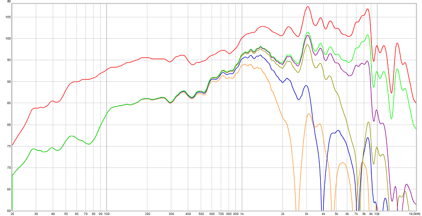
.....😛 room response prediction for White Fangs guitar cube using 27 liters enclosure based on Visaton's BG 20 datasheet curve seen below as the lifted red trace with a offset of +6dB, there's a chance baffle used for creating datasheet curve have some baffle step loss and difraction somewhere and will error in this prediction but in think they used a big baffle error will be below 200Hz or so and don't move much in this prediction. Math used to manipulate factory curve was in first step a Linkwitz transform from drivers free air numbers Qts of 0,44/38Hz to Q of 1,0/86,4Hz (Sealed cube), second step was baffle step loss and diffraction, third step was room boundary reinforcement and pressurization gain in a room with 16 feet as longest dimension and cube position was 3 feet above floor 4 feet from rear wall and 5 feet from side wall, fourth step was add beaming data off axis for a 165mm piston at 10º/20º/40º/80º, so green trace below is the on axis prediction, purple at 10º etc.
Attachments

Last edited:
That sounds great, I like the idea of the square "baffle plate" becoming the "membrane". Any chance you could try it first without any holes? Just curious.
edit: You make a great point about wanting to get the square to vibrate more freely than the other pieces.
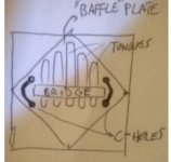
I was thinking just a couple of "sound holes" not like the ones in guitars, more like the c-holes or f-holes in viols and violins, more a slit to allow for the bridge to move more freely, since otherwise it might be too rigid, held by the two corners. If you imagine the square side standing with one side pointing downwards, then the bridge will be along the diagonal, and I was thinking using just a couple of C-shaped slits on either side.
Sorry for the ASCII art, something like this:
Code:
            +
        +      +
    +              +
+   ( ===== )   +
    +              +
         +    +
            +
the ===== is the bridge -analogous to the driver-, the ( ) would be the soundholes.
Do you think it would change the acoustics of the box too much? I have seen all marimbulas, rhumba-boxes, etc, they have either many round holes, or a big one like a half moon on the top side of the bridge. I think this approach will keep them to a minimum (does it start qualifying as a ported box? he he he)
Thank you for your input.
Cheers,
WF
PS: my drawing was ruined... sorry, there is some function that takes away all the spaces..
.....😛 room response prediction for White Fangs guitar cube using 27 liters enclosure based on Visaton's BG 20 datasheet curve seen below as the lifted red trace with a offset of +6dB, there's a chance baffle used for creating datasheet curve have some baffle step loss and difraction somewhere and will error in this prediction but in think they used a big baffle error will be below 200Hz or so and don't move much in this prediction. Math used to manipulate factory curve was in first step a Linkwitz transform from drivers free air numbers Qts of 0,44/38Hz to Q of 1,0/86,4Hz (Sealed cube), second step was baffle step loss and diffraction, third step was room boundary reinforcement and pressurization gain in a room with 16 feet as longest dimension and cube position was 3 feet above floor 4 feet from rear wall and 5 feet from side wall, fourth step was add beaming data off axis for a 165mm piston at 10º/20º/40º/80º, so green trace below is the on axis prediction, purple at 10º etc.

Thanks a lot BYRTT, I will look at it closely. BTW, what software did you use?
Cheers,
WF
I have been staring at your graph, BYRTT, I'm afraid I am trying to decipher it but I don't really understand it. The red curve is the one provided by the manufacturer?
I see some of the later curves produce horrible comb filter effects, I guess this is from room reflections, right?
Could you tell me if an enclosure larger than 27 litres would be any better? I mean, I have seen one site saying the ideal sealed enclosure for this driver would be something like 1.66 cubic feet (46 liters) and then I used some software that says the ideal would be 74 liters.
Could you simulate those volumes and explain to me if I would gain anything?
Cheers, and sorry for my utter ignorance in speaker design,
WF
Hi again,
this is what my ASCII -failed- drawing wanted to depict.
The "soundboard" of the marimbula being on the truncated square face it acts somewhat like the speaker, at least as I see it, instead of being driven by electromagnetic force, it's done by just pulling on those steel tongues.
Cheers,
WF
this is what my ASCII -failed- drawing wanted to depict.
The "soundboard" of the marimbula being on the truncated square face it acts somewhat like the speaker, at least as I see it, instead of being driven by electromagnetic force, it's done by just pulling on those steel tongues.
Cheers,
WF
Attachments
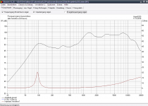
...the impedance peak in the hypercube at 91Hz is fully in line with the simulation of a 17,7liters sealed box in the Visaton Boxsim software
This is what my simulator sys about B200 in 17.7 litres (no damping).
dave
Attachments
WF,
I was just guessing that keeping the holes to a minimum might make the resonance more broad (even), but maybe at the expense of making the instrument too soft(?) Anyway, I like your idea of the holes being in the corners. I think you should follow your instinct; I get the sense you have a good feel for this and I don't want to screw it up. 🙂
I was just guessing that keeping the holes to a minimum might make the resonance more broad (even), but maybe at the expense of making the instrument too soft(?) Anyway, I like your idea of the holes being in the corners. I think you should follow your instinct; I get the sense you have a good feel for this and I don't want to screw it up. 🙂
...My opinion is, though, that the smallest volume approach is correct and I have very good behaviour of the B200 in it...
Hope not i'm irritating but why use the smallest volume do you use some smoothing EQ or have a room null to fill out there, back in post 610 i showed below prediction for B200 in 17,7 liters having a +6dB overshoot although i did manipulate or offset the original simmed 104Hz Fsc down to 91Hz just to be agreement with your impedance graph, about acoustics in normal indoor rooms and longer measurement window one would probably never notice that overshoot but its there and with Jeff Bagby's few milimeters centered nearfield measurement method it should reveal itself.
...FWIW, the impedance peak in the hypercube at 91Hz is fully in line with the simulation of a 17,7liters sealed box in the Visaton Boxsim software. So here we have no difference in behaviour...
Agree and use same software as planet10 that 91Hz is not inline with B200 into 17,7liter, could it be Boxim automatic adds say about 10-20% stuffing so it ends down at 91Hz instead of 104Hz at a clean 17,7 liters volume, if so your real world build should also have that stuffing installed else its not in agreement with Boxim software.
...Sonce's shot at the lower impedance in the box makes no sense to me. I compared with simulation software and did not find that impedance in a box is modeled to be lower. Also, flexing walls would mean higher impedance like without enclosure, IMO. I may be wrong.
So lower impedance would indicate special behaviour of the hypercube. As far as I remember, Tesserax had some measurements done, maybe he can chime in.
Could be wrong but will imagine lower impedance means a overmuch stiffer spring and more amp power to move that point of stiffness, phenonem is probably caused by form of cone is more or less replicated at apex in back of enclosure so same spring pressure effect gets uniform loaded mostly all over cones shape verse a normal enclosure that has a plane back that will never load coneshape so hard because of weak angels and also into corners air can stand still and kind of isolated difuse aroud itself.
Last edited:
Thank you Planet10 and Byrtt,
indeed, I hadn't noticed that the enclosure definition added some stuffing without my intention, namely 6,7g/liters of stuffing.
When I remove this in the software, I get the same plots as you.
So this is really something - the hypercube behaves as if it was stuffed! I like this.
Here is the original sim (which is for the stuffing with 6,7g/l):
Attachments
Thanks a lot BYRTT, I will look at it closely. BTW, what software did you use?
Cheers,
WF
Its all nice practical freeware stuff used although note such stuff has most often some learning/educating curve to handle but that should be no problem if interest really is there : ) its late so will get back tommorrow with some links.
I have been staring at your graph, BYRTT, I'm afraid I am trying to decipher it but I don't really understand it. The red curve is the one provided by the manufacturer?...
Yes red trace is manufactures pure datasheet curve, all i did to it is offset it +6dB so it stays clear in graph/plot of the others predicted curves.
...I see some of the later curves produce horrible comb filter effects, I guess this is from room reflections, right?
...
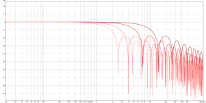
Its when going off axis on a relative big diameter piston we loose high frequency program more and more the worse the axis and reminds why drivers are manufactured in different sizes and some build multi way systems, problem is not there being situated pure on axis but bigger diameters as this BG 20 can for example only hold 20khz within a very few degrees off axis and called it beams as crazy : ) Up to about 1500Hz it radiate perfect uniform 180º around also called it radiate perfect into half space, from about 1500Hz and up it starts beam and comb filtering as seen below for 10º/20º/40º/80º off axis. Mostly because beaming is a problem at all hang together that room reflections mix with direct sound called power response and here a 165mm piston will sound kind of dull because for example say it adds about 40% to direct sound below 1500Hz but almost nothing as frq goes up above 1500Hz and more. Then again multi way systems have kind of same power response problem even they use a perfect small tweeter piston down at say 20 mm diameter but their power response problem sits only inside XO region where tweeter hand over to midrange and spacing distance between those two drivers is the culprit, where had it been a coxial driver with same acoustic center then power response can get kind of perfect. That said in your use for musical instruments beaming can maybe be good enough feature or maybe better or at least if one knows of it one can take care where to physical place the stuff on the scene or in rehearsal room.
20dB down there is kind of traffic going on 😀...
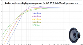
...Could you tell me if an enclosure larger than 27 litres would be any better? I mean, I have seen one site saying the ideal sealed enclosure for this driver would be something like 1.66 cubic feet (46 liters) and then I used some software that says the ideal would be 74 liters.
Could you simulate those volumes and explain to me if I would gain anything?...
Five simulations below and guess for guitar use the smallest one are fine but don't go smaller then overshoot on blue trace probably gets too hot/colored and maybe starts conflict with some other room gains and can sound really nasty, then again this is not for a smooth flat reference but musical instruments so who will know : ) for bass guitar and acoustic guitar use with reference to light green trace in post 624 will suggest some EQ filters somewhere in chain to flatten out a smoother and lower reaching response but guess for distorted electric guitar it doen't matter so much : )
Attachments
Last edited:
Wow, thanks a lot BYRTT, I don't quote the whole message because it will fill in too much space, but I read it carefully.
I wished I understood better these things, but I am already overwhelmed by the amount of articles and books I want to read, and stuff keeps on piling and the pile getting bigger... So I guess I will leave speaker design for another life! Although building them seems like fun, and anyway, I already have the drivers.
My respect to everyone here who understands fully all this info, and thank you so much for the simulation.
From it I gather that there is a trade off in enclosure volume, when the volume is smaller, the bass drops earlier, and it creates some kind of resonance, almost like if you applied a "highpass" filter with "resonance", borrowing from synth-talk.
With bigger volumes, the bass response is flatter, and it extends more into the bass region, things that are both desirable, but then again who will want a 400 liter guitar cabinet to carry around?
So, I think I will opt for the 'reasonably' bigger volume, and not use the smallest box where the drivers could fit.
I will love to give back to this community some test results, I have a "supposedly" flat response test mike somewhere, but I will probably need some coaching on how to proceed.
Thanks to all of you for your feedback, cheers,
WF
Just wondering, is there a reason the ~70 volume performs so bad? It is really so, it extends no further into the bass than the 45 l. version, and it starts rolling off earlier.
From the graph, the 26.5 l and 45 l seem like the best options. Actually 45 seems a good compromise, the bass response is flatter and you get some extended bass, plus 45 l. is quite manageable. BTW, there is a website that says this is the best option:
"Optimum Cabinet Size (determined using BassBox 6 Pro High Fidelity suggestion): 1.66 feet^3"
Visaton BG20-8 8" Full-Range Speaker with Whizzer Cone 8 Ohm
The builder recommends 30 l., so I guess that is the optimum range for these drivers (~30-45 l.).
BG 20 - 8 Ohm | Visaton
Thank again, to all of you, for the your suggestions and commentaries posted here in this forum, cheers,
WF
I don’t think 70L curve looks bad at all. That’s a nice smooth roll off. Why do you say it is bad? Vas is 110L and you can make a sealed cabinet up to Vas and it will work fine. Basically the softer the suspension is coupled with a weaker motor, the larger the Vas.
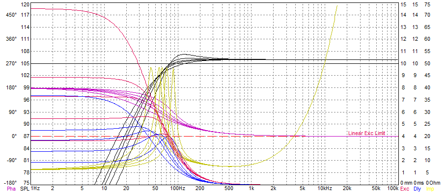
White Fang funny you wonder about the yellow one because its the magic 2nd order butterworth curve hitting a Q value of 0,7071 which gives widest amplitude flatness compromise before rolloff and its corner frq is exactly at -3dB point where the higher or lower Q values relative to 0,7071 number will give some amplitude overshoot or undershoot also called over and under damped, and by the way these filter grades are exactly the same that happens into electric circuits combining a capacitor and inductor. Some builders would probably mean its magic to hit that Q of 0,7071 using impedance measurements and adjust physical volume with stuffing and bags of rice inside enclosure until impedance measurement number is exactly at 0,7071, thoughts behind it is probably it would then mean friction to move cone in inwards verse outward direction is then same and in kind of symetric balance, but then again there exsist some published advanced Klippel tests of various drivers and here many drivers even the most costly ones don't look in very good or perfect linear balance and are often offset mechanical somewhere by purpose so not shure its worth go for theoretical symmetry.
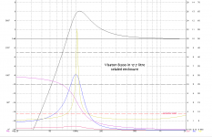
Another lesson is in a way its probably not free to pick between those extensions because system acts as a spring and Q value numbers in a way is springs tension and will dictate lenght of stroke when pushed with a certain power, in previous plot curves show power of 1 watt at 1 meter, below is at 25 watt power and includes a red line showing limit of linear excursion (length of stroke) at 4 milimeter point, and as seen on the 5 times red traces its actual only the small one that goes below limit at 25 watts but then again system now outputs +106dB SPL and that high SPL is probably not needed so try find a balance. Visaton don't tell milimeters for highest mechanical excursion limit any where so we don't know where unit will hurt or detroy itself mechanical therefor think use either the blue or purple volume value to keep stoke within some predictable limit. Last thing is if you add dampening material it adds virtual volume that driver incuding spring effect will see, it is said up to about 30% more volume if enclosure is hard stuffed.
Another lesson is in a way its probably not free to pick between those extensions because system acts as a spring and Q value numbers in a way is springs tension and will dictate lenght of stroke when pushed with a certain power, in previous plot curves show power of 1 watt at 1 meter, below is at 25 watt power and includes a red line showing limit of linear excursion (length of stroke) at 4 milimeter point, and as seen on the 5 times red traces its actual only the small one that goes below limit at 25 watts but then again system now outputs +106dB SPL and that high SPL is probably not needed so try find a balance. Visaton don't tell milimeters for highest mechanical excursion limit any where so we don't know where unit will hurt or detroy itself mechanical therefor think use either the blue or purple volume value to keep stoke within some predictable limit. Last thing is if you add dampening material it adds virtual volume that driver incuding spring effect will see, it is said up to about 30% more volume if enclosure is hard stuffed.
Attachments

Last edited:
Thanks BYRTT, what I like about the purple curve is that it extends somewhat more into the bass with a gentle boost or resonance before. The "magic" .707 curve might be flatter, but is outperformed clearly by the blue and purple ones in the bass. That being said, the smaller volume might create too much of a boost there at around 120 Hz.
I will follow your recommendation gladly, also, in case the driver kills itself by going too far, well, these are not very expensive ones anyway.
I will start building them and report on how is everything going along the way. I wish a nice weekend to the whole diyaudio "team". Cheers,
WF
I will follow your recommendation gladly, also, in case the driver kills itself by going too far, well, these are not very expensive ones anyway.
I will start building them and report on how is everything going along the way. I wish a nice weekend to the whole diyaudio "team". Cheers,
WF
I don’t think 70L curve looks bad at all. That’s a nice smooth roll off. Why do you say it is bad? Vas is 110L and you can make a sealed cabinet up to Vas and it will work fine. Basically the softer the suspension is coupled with a weaker motor, the larger the Vas.
To me the extra flatness of the curve seems at the expense of the bass performing less, so I don't get why this is an ideal situation at all.
I was yesterday tuning the harpsichord for Handel's Resurrezione, I noticed the concert hall had every wall covered with diffusing panels.
Did anyone tried that on speaker walls? Is it worth to add some texture to the surface? Not that very hard to do with a router. Just a few passes at different levels, you won't even see it from the exterior.
Cheers,
WF
- Status
- Not open for further replies.
- Home
- Loudspeakers
- Full Range
- Hypercube Loudspeakers