It trully makes that difference. I built several amps with 0.005 THD class AB BJTs, class B current-out opamp ones... none compares to this one.

I managed to further reduce distortion 10 times to about 0.018 % (0.1 Watt to 2 Watts) and keep THD profile almost unchanged, helped by a 'minor' change of an active device.
I wanted to start a new thread with my little discovery, but I considered this not very elegant, as Diego is this thread's originator and inventor with his LM317 curious-style, very efficient CCS.
I wanted to start a new thread with my little discovery, but I considered this not very elegant, as Diego is this thread's originator and inventor with his LM317 curious-style, very efficient CCS.
Last edited:
It's interesting that you found that decrease in distortion with the change of the active element. The circuit that begins this thread is in some way a free project subject to changes and improvements by those who prefer it.
It doesn't bother me at all that you incorporate your ideas and measurements into this same thread. It would be interesting to have the comparison between versions with as many parameters as possible to measure (frequency response, distortion profile at different powers and frequencies, etc.).
A pleasure that you can experience from my humble circuit. 👍👍👍
Not a humble circuit, at all. And I apologise, I deleted by mistake the bottom of my message, this is:
The change: I replaced the IRFP140N MOSFET with a BJT DARLINGTON TIP122.
The change: I replaced the IRFP140N MOSFET with a BJT DARLINGTON TIP122.
Thanks for the heads up, it’s appreciated.
My PCB should arrive within the next few days.
My PCB should arrive within the next few days.
Good finding. Did you keep the R2/R1 ratio and did you change something else besides the TIP122?The change: I replaced the IRFP140N MOSFET with a BJT DARLINGTON TIP122.
Was reduction of distortion also a noticable improvement in sound?
I am waiting for the delivery of PCBs to arrive.
Hi, I kept power resistors ratio unchanged, at 0.55 - current draw 810 mA. R1=1ohm, R2=0.55 ohms)
But R6/R5 is now 3300 ohms/ 330 ohms, theoretical gain of 10.
The Darlington transistor behaves waaaaay better than the Mosfet (I think after I heard it). But please note that you need to adjust bias pot again to symmetric clipping.
In my case, I use a 20.4V smps laptop supply (vvv quiet) and I found the sweet spot at 9.0V bias, measured at the transistor collector to ground.
THD around 0.02% from 100mW to 2W, with H2 dominant.
Hope this helps,
Bests,
Radu
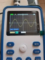
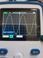
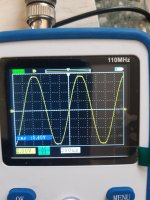
I attach three photos showing max input level from a portable cd player, of 631mV, and the consequent max amplifier output level of 5.4V RMS with perfect, symmetrical clipping, offset voltage of 9V. The 4.97V RMS output, or about 3 Watts, is the max level at which sine wave looks perfect, shortly before clipping.
Hope this helps!
PS: I reckon, the idea of using a Darlington in the final stage(s), came to me from an older post of a famous Italian audio designer on redcircuits.com.https://www.redcircuits.com/Page177.htm, although his design is totally unrelated to Diego's.
Then, I discovered from datasheets that cheap TIP122, TIP 120, or 121 in TO220 case have huge current gain at rather small amperage compared to their bigger size cousins TO247 Darlingtons, and much smaller input capacitance.
Attachments
Today’s little surprise 😄. Julian’s PCB.
My heatsink can dissipate about 60W so I’ll use them for another amp. and use much smaller one for this desktop amp.


For the output BJT, if you need a Darlington type TO-247 type you could use the TIP142 which I believe has been used as a substitute on the Pass A40 👍
My heatsink can dissipate about 60W so I’ll use them for another amp. and use much smaller one for this desktop amp.
For the output BJT, if you need a Darlington type TO-247 type you could use the TIP142 which I believe has been used as a substitute on the Pass A40 👍
Last edited:
Try TIP142 👍 instead of TIP122.Hi, I kept power resistors ratio unchanged, at 0.55 - current draw 810 mA. R1=1ohm, R2=0.55 ohms)
But R6/R5 is now 3300 ohms/ 330 ohms, theoretical gain of 10.
The Darlington transistor behaves waaaaay better than the Mosfet (I think after I heard it). But please note that you need to adjust bias pot again to symmetric clipping.
In my case, I use a 20.4V smps laptop supply (vvv quiet) and I found the sweet spot at 9.0V bias, measured at the transistor collector to ground.
THD around 0.02% from 100mW to 2W, with H2 dominant.
Hope this helps,
Bests,
Radu
I haven’t checked the pinout yet but this is what I’ll use.
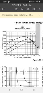
The only problem with the bigger TIP142 is that manufacturer datasheet lacks any graphs referring to its gain against current... and it only says that an Hfe of 1000 is reached at 5A.
In contrast, the TIP122 datasheet has plenty of very useful graphs -see above- including one showing a gain of 1000 at 200 mA and of about 3000 at 1A.
In contrast, the TIP122 datasheet has plenty of very useful graphs -see above- including one showing a gain of 1000 at 200 mA and of about 3000 at 1A.
I replaced TIP122 with a 2-transistor Sziklai pair, and THD rose to about 0.6% at 1 Watt - totally unnacceptable.
Then, I used an IRFP150N, THD grew to 1% at 1 Watt... maybe my Mosfet was a fake one.
Best, smallest, distortion is given - so far- by a humble Darlington TIP122 transistor, followed by an IRFP140N with 0.2% at 1 Watt.
Hope this helps.
Then, I used an IRFP150N, THD grew to 1% at 1 Watt... maybe my Mosfet was a fake one.
Best, smallest, distortion is given - so far- by a humble Darlington TIP122 transistor, followed by an IRFP140N with 0.2% at 1 Watt.
Hope this helps.
Beyond the absolute value of THD, ¿have you been able to compare the distortion profile between these MOSFETs and the bipolar Darlington transistor?
Would be interesting to analyze the cadence between the spectral components of distortion. Another interesting point to measure and compare would be the frequency response and slew rate between the two transistor technologies.
Would be interesting to analyze the cadence between the spectral components of distortion. Another interesting point to measure and compare would be the frequency response and slew rate between the two transistor technologies.
First of all: a R2/R1 ratio of 1:1 is crucial to obtain the 'nicest' tube-like distortion profile - I didn't believe it until I tried it...
From this point, I found out that there's almost no difference in distortion cadence among the several Mosfets I used for tests and Darlingtons/Sziklai pairs. But there is difference in distortion overal levels among them, as I said above.
For the other part of the tests, I reckon that I do not know how to conduct them, FR or the slew rate one...I'm just a junior in Arta software.
OK👍👍👍. I'll see if i can find the time to do some comparisons over the next few days. If I can do it using test bench measurements, even better.
I'll soon be introducing a higher-power version, something like 16.2 W RMS into 8 ohms per channel (about 32.4 W RMS in stereo). The schematic that started this thread achieves 4.24 W RMS into 8 ohms per channel, or about 8.48 W RMS in stereo.
I'll soon be introducing a higher-power version, something like 16.2 W RMS into 8 ohms per channel (about 32.4 W RMS in stereo). The schematic that started this thread achieves 4.24 W RMS into 8 ohms per channel, or about 8.48 W RMS in stereo.
Yes, it's developed from the initial circuit in this same thread. I just need to polish a few details before uploading it and, if possible, test it. It won't be very different from what you already know, just maximize the capabilities of each element a bit.
- Home
- Amplifiers
- Pass Labs
- Hybrid ZEN Amplifier + LM317 = Efficient and simple