This weekend I'm testing the current board with different resistor values to lower the standing current in the output SOT-223 fets. I'll also be taking a Dremel tool to the piece of PCB heat sinking land that sticks under the line stage input coupling cap. I'm hoping for decent gain-phase plots once I do that...
OK, I changed resistor values to lower standing current in the gain blocks, though each tube 1/2 still gets 5 mA bias current. Here are the gain-phase plots for the line amp. I may or may not proceed with the new layout, as the lower bias current will reduce the temperature for the SOT-223 output fet for each gain block. I will need to add a a bias network network for the RIAA 2nd stage to boost the output voltage and output fet standing current. The line amp, however looks fine with the new resistor values and a reversion to the 2-capacitor compensation scheme.
Attachments
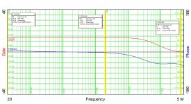

One of the things proven by this G-P run was my diagnosis of the peaking problem in the previous plots. Cutting away the section of the PCB heat sinking trace (connected to output drain) that was under the input capacitor of one line amp channel got rid of the peaking response and restored normal operation. The trace under the input cap was supplying capacitively coupled positive feedback and causing the peaking. Feedback can happen in sneaky ways...
I spent a fair portion of last evening cleaning up the reference designators on the new layout for this preamp. I may send out for boards tonight...
Nice!
I’ve been watching this thread with interest, it’s been pretty quiet from us in the peanut gallery, but I’m sure there’s a bunch of us waiting to see how this all turns out.
Also, have you mentioned anything about the PSU requirements? The schematic says 150v B+ and the filament appears to be in series, so 12v?
Actually, I'll be running all 3 tubes in series with a 19V laptop adapter and a small dropping resistor. The +150V will be supplied from a DC-DC converter of my own design, also running off the 19V adapter. I have the boards in for the DC-DC converter, but haven't gotten around to populating them just yet. That might happen over the long weekend.
Last edited:
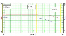
OK - I ran gain-phase plost on the line amp and on side of the phono stage. The line amp looks OK (both sides), and one sode of the phono amo is OK as well.The other side of the phono amp is out of sync with DC and AC results. This may be a reaction to improper design or a defect on the boards I got back from PCBway.I may be looking for another board vendor, as this is not the first circuit mishap I've seen for boards that are nomilally laid out OK.
Attachments

I figured out the problem with the other RIAA channel of the preamp - it was my bad, and a touch with the Dremel fixed it right up... I'll be running the gain-phase for that channel tomorrow. After that, it's just a matter of bringing up a suitable DC-DC converter to supply +150 VDC from the 19V switching adapter.
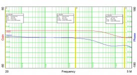
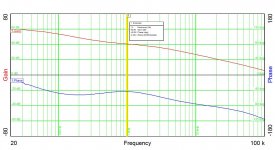
Here's the gain-phase scan of the 2nd RIAA channel that was giving me conniptions for a while - trouble is, when you use surface mount parts, sometime they look like they're soldered when they actually aren't... Fixed, anyway. The gaon-phase scan shows a close match with the other RIAA channel.
Attachments
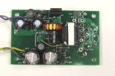
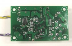
I have a DC-DC converter board that was originally paired with the first version of this preamp using subminiature tubes and an all-semiconductor line stage. I'll be rewinding the transformer on that board for 19 VDC input. I figure if I plop the converter into a die cast aluminum box with feedthrough caps and a common - mode inductive filter to clean up the output, I'll be cooking with gas...
I may go back and re-tool this design so that it can also accept the Russian submini dual triodes as well as the 6N3P-E. The filament draw is similar for both tubes, probably making the little submini triodes as hot as a pistol..
I fired up the little DC-DC on the bench with around 90 mA load, and temperatures are 50C and below, with the transformer the hottest thing on the board. Efficiency is 93-94%, and operating frequency is around 70 kHz.
This afternoon, I ran the preamp from a bench supply. driving both the filaments of the 6N3P-E tubes in series, plus the high voltage as generated by the DC-DC converter. The preamp drew 19V at 0.96A, representing both the filament load and the HV as generated by the DC-DC converter
I'm looking at a regulated option for the HV DC-DC converter using the venerable TL494 controller. The topology is a push-pull variant of a boost converter using the dead time option of the controller to vary overlap between the two phases to regulate the output voltage. Bench tests on the breadboard look promising.
- Home
- Source & Line
- Analogue Source
- Hybrid RIAA/Line Amp