How many reactance is the optimal when I calculate the value of the shunt cap and on which frequency?
I mean this by a "standard" voltage divider, in my original question.
Optimal for what? I would shoot for something below 5Hz at least. A series resistor of 5k and a 10uf cap would give you an F3 of around 3Hz. If you want to use a smaller film cap, then use a higher value resistor. Or, if the bias supply is quiet enough, leave it out altogether.
Sheldon
Thanks Sheldon!
I thought the target frequency is 50Hz or 100Hz against humm.
Only one more question:
What could be the "optimal" imput impedance of a mosfet source follower?
I know it dependinig on the driver's output impedance, but I ask this from the mosfet's point of view.
Tyimo
I thought the target frequency is 50Hz or 100Hz against humm.
In this example the cap is after the series resistor or before (from the middle point of the voltage divider to the ground)?A series resistor of 5k and a 10uf cap would give you an F3 of around 3Hz. If you want to use a smaller film cap, then use a higher value resistor.
Thanks! It was the most important for me.If you want to use a smaller film cap, then use a higher value resistor. Or, if the bias supply is quiet enough, leave it out altogether.
Only one more question:
What could be the "optimal" imput impedance of a mosfet source follower?
I know it dependinig on the driver's output impedance, but I ask this from the mosfet's point of view.
Tyimo
Very interesting amplifier. Still, I would think putting the cathode to GND and using a bias voltage and (the best possible foil) cap on the grid would be better than using any electrolytic in hte cathode circuit....
thats what I am doing....
just my two cents...
thats what I am doing....
just my two cents...
Another hybrid circlotron
Hi all,
Did something similar a few years back.
http://www.diyaudio.com/forums/pass-labs/75644-my-jfet-project.html#post1116433
I did a few changes compared to the one in that thread but it basically looks as described. It sounded very good, dry dynamic and a little rolled off in the top end. The best part was actually the bass, dry, deep and dynamic!
//Anders
I thought the target frequency is 50Hz or 100Hz against humm.
'tis, but you want to be well below that to completely suppress it. A little overkill is not a bad thing here.
In this example the cap is after the series resistor or before (from the middle point of the voltage divider to the ground)?
The series resistor is between the wiper and the cap.
What could be the "optimal" imput impedance of a mosfet source follower?
I know it dependinig on the driver's output impedance, but I ask this from the mosfet's point of view.
Not sure what you are asking, and I am by no means an expert on this. That said, I would think that you want some path to ground to drain any static charge from the gate, if it is DC isolated from the rest of the circuit, but I would think that something in the MOhm range would be adequate. In this design, there is already a low impedance path to ground via the bias supply.
Sheldon
Very interesting amplifier. Still, I would think putting the cathode to GND and using a bias voltage and (the best possible foil) cap on the grid would be better than using any electrolytic in hte cathode circuit....
thats what I am doing....
just my two cents...
Or just a couple of diodes (or transistor connected as diodes) in series.
Sheldon
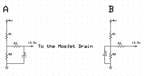
I attached a little drawings for better undrestanding. Do you mean the A or the B version? Usually people use the B.The series resistor is between the wiper and the cap.
Not sure what you are asking, and I am by no means an expert on this.
I mean on "optimal" input impedance as my friend Lineup wrote:
Today Normally used input impedance for power amps is:
10.000 - 22.000 Ohm
The rule is:
If you can,
keep input impedance as low as possible.
This will transport more micro currents ( uA, uAmpere )
in your signal cables,
even if you input voltage is a as low as 0.1 Volt RMS.
So, the question: What is better for the Mosfet sourcefollower? 10K or 100K?
Tyimo
Attachments
Last edited:
I attached a little drawings for better undrestanding. Do you mean the A or the B version? Usually people use the B.
B
I mean on "optimal" input impedance as my friend Lineup wrote:
Today Normally used input impedance for power amps is:
10.000 - 22.000 Ohm
The rule is:
If you can,
keep input impedance as low as possible.
This will transport more micro currents ( uA, uAmpere )
in your signal cables,
even if you input voltage is a as low as 0.1 Volt RMS.
So, the question: What is better for the Mosfet sourcefollower? 10K or 100K?
Still not sure what you are getting at. Do you mean; what is the optimal impedance for the mosfet source follower to drive? If so, that depends on the circuit, and your distortion requirements. But, a typical power mosfet follower in a TO 220 package can easily drive much lower than a 10k load. The circuit in this thread is a large power mosfet driving an 8 Ohm load, so that should tell you something.
Sheldon
I mean: how many input impedance is optimal for the mosfet power source follower. (When we choose the value of this resistor coming from the voltage divider) High or low imput impedane gives better sound?
Some people says lower is better. Like 10-20K
Some people says lower is better. Like 10-20K
Member
Joined 2009
Paid Member
I think you mean the output impedance of the driving stage not the input impedance of the follower. The output impedance of the driving stage should be as low as possible. But maybe you ask about gate stopper resistors.
No!!!!
I mean the input impedance of the Mosfet Power Follower stage. 🙂
🙂
Some people want to set it high, for example 100K or even higher, because it is better for tube preamps, but some people says lower input impedance is better, for example 10 or 20K because the keep input impedance as low as possible.
This will transport more micro currents ( uA, uAmpere )
in your signal cables, even if your input voltage is a as low as 0.1 Volt RMS.
But slowly I will give up. Nobody want to understand this question....
I mean the input impedance of the Mosfet Power Follower stage.
🙂Some people want to set it high, for example 100K or even higher, because it is better for tube preamps, but some people says lower input impedance is better, for example 10 or 20K because the keep input impedance as low as possible.
This will transport more micro currents ( uA, uAmpere )
in your signal cables, even if your input voltage is a as low as 0.1 Volt RMS.
But slowly I will give up. Nobody want to understand this question....
No!!!!
I mean the input impedance of the Mosfet Power Follower stage.
Some people want to set it high, for example 100K or even higher, because it is better for tube preamps, but some people says lower input impedance is better, for example 10 or 20K because the keep input impedance as low as possible.
This will transport more micro currents ( uA, uAmpere )
in your signal cables, even if your input voltage is a as low as 0.1 Volt RMS.
But slowly I will give up. Nobody want to understand this question....
I finally understand the question, but there is no value that works in general. It depends on the system. If your driving source has a low output impedance and can source enough current to drive the signal to the levels you require for a low input impedance, then it's better to keep it low. Low impedance will keep noise levels down. And if your source can't drive a low impedance load, then it has to be higher. So, the lowest input impedance that meets your goals is what you should generally choose. Lower than what, higher than what? The answer to that requires a circuit and the designers priorities. Is noise the limiting factor, or is distortion the limiting factor. What's your happy medium for the circuit?
Sheldon
Thanks Sheldon! This is what I meant.Low impedance will keep noise levels down. And if your source can't drive a low impedance load, then it has to be higher. So, the lowest input impedance that meets your goals is what you should generally choose.
What's your happy medium for the circuit?
Nothing special. Just wanted to know another people's oppinions.😉
Greets:
Tyimo
Hello,
I should receive this week the power supply transformers to complete this project.
In these days I have upgraded the my old Hybrid 2010, see here the incredible result
Hybrid Amplifier by Andrea Ciuffoli
I should receive this week the power supply transformers to complete this project.
In these days I have upgraded the my old Hybrid 2010, see here the incredible result
Hybrid Amplifier by Andrea Ciuffoli
Member
Joined 2009
Paid Member
You arrived here too ! - tube front end driving BJT diamond buffer. It's what I have for my Cellini 2 hybrid.
Hello,
I should receive this week the power supply transformers to complete this project.
In these days I have upgraded the my old Hybrid 2010, see here the incredible result
Hybrid Amplifier by Andrea Ciuffoli
You shout replace the 5W wire wound by metal oxide resistors Andrea.
Sorry if this is seen as threadjacking, but would it make sense to drive the circlotron power stage by something like Susan Parker's MosFet preamp?
Audiophonics -
Audiophonics -
Helmuth , 5w resistors ?
I think so why put in wire wound there are nice thick-film or metal oxidetypes.
A wire wound resistor is a coil and that can have effect on your harmonics when it finds a way to resnonate.
Helmuth , where you see the 5w resistors ?
el`Ol, Would you like to use a mosfet instead of vacuum tube as drive ?
el`Ol, Would you like to use a mosfet instead of vacuum tube as drive ?
- Home
- Amplifiers
- Tubes / Valves
- Hybrid Circlotron Amplifier with only 3 components on the signal path