Yea!!!🙂Quanghao.com can produce the pcbs for the DC filament power supply and the soft-start protection at a very low cost.
---------
New info has been updated on the web page.
Tyimo,
there is no dc lost on the transformer secondaries because the mosfet is an open circuit for the dc.
The bias voltage depend by the mosfet used so you must measure 1A or 1.6A on choke (I=V/R=V/0.16ohm).
If you use a power supply without the choke you can add a 0.1ohm in series to the mosfet drain to measure the bias current.
The DC filaments is not necessary for this design and it is possible to use any protection circuit like the one used in my Hybrid 2010.
Thanks!
I thougth +3.5Vdc on the Gate is too high for the 2Sk1058.
It is usually ca. +1.5Vdc, it isn't it?
I thougth +3.5Vdc on the Gate is too high for the 2Sk1058.
It is usually ca. +1.5Vdc, it isn't it?
But I am not sure that the simmetric design sound better than normal
I hope to test both in the future
I hope to test both in the future
PCB
Hopefully a complete PCB can be offered when the design is "final".
Hopefully a complete PCB can be offered when the design is "final".
Quanghao.com can produce the pcbs for the DC filament power supply and the soft-start protection at a very low cost.
---------
New info has been updated on the web page.
But I am not sure that the simmetric design sound better than normal
I hope to test both in the future
Worth to try Tube symetric(PP) driver for sure and to made some comparison listening test-Simetric drive vs SET driver.But think that symetric Tube drive configuration is more for best sound performance sensitive than original simple non GNFB SET driver.
Just think next,since you have there plenty of low impedance drive voltage/ current on the interstage Transformer secondary, you can rise the Amps out power & lower the Amps out impedance by adding more SS N Fet in parallel for Circlotron out power A class stage,(of course than PSU have to be more powerfull designed to).
Best Regards Audiodesign

boudy,
no, the pcb are only for optional soft start + protection + button and for DC filament with soft start so you can ask now to Quanghao.com
This amplifier can be build without pcb if you buy a protection module on Ebay.
no, the pcb are only for optional soft start + protection + button and for DC filament with soft start so you can ask now to Quanghao.com
This amplifier can be build without pcb if you buy a protection module on Ebay.
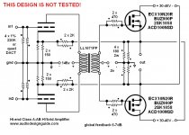
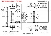
Here the last balanced version simulated with Winspice
If we want to use some feedback it is necessary use the D3a in triode connection to have a voltage stage with 70x.
It is necessary use the LL1692A instead of LL1671 to increase the primary inductance.
I hope to test it soon.
If we want to use some feedback it is necessary use the D3a in triode connection to have a voltage stage with 70x.
It is necessary use the LL1692A instead of LL1671 to increase the primary inductance.
I hope to test it soon.
Attachments
Audiodesign!
Do you know how to calculate the value of the shunt capacitor in the voltage divider???
I see many different values from 0.47 MKP to 2000uF ELKO😕
Tyimo
Do you know how to calculate the value of the shunt capacitor in the voltage divider???
I see many different values from 0.47 MKP to 2000uF ELKO😕
Tyimo
Hello!
What do you think the usage for SemiSouth SJEP120R100 J-FET instead of 2SK1058?
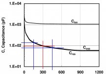
I would avoid these in this design. Those SiC JFETs need to operate at high voltages (see attached) to keep the internal device capacitance both down and linear. At the usual MOSFET/BJT voltages, the SiC JFET has a capacitance that is enormous and nearly vertical. That will make for driving difficulties, and likely sound like
An externally hosted image should be here but it was not working when we last tested it.
.This is an OTL design, and I would prefer to have an OPT between me and 300Vdc. Hollow state OTLs that operate at about 110Vdc are bad enough as it is.
Attachments
Yes. For example in your bias supply ther is a 0.47mF MKP shunt cap.
But generally I would like to know it.
But generally I would like to know it.
Yes, I know, but how can I calculate the value? Is there any rule???
I would like to learn it.
I would like to learn it.
Donn't you mean the Gate????to close the mosfet source circuit to ground
The 0.47uF is necessary to close the mosfet source circuit to ground
Except in that configuration it's not doing much, other than sometimes reduce HF. With the wiper at the top, the cap does nothing. With the wiper at the bottom, the F3 is about 350Hz. The solution is to use a resistor in series with the wiper and put the cap after the series resistor. If the series resistor is several times larger than the pot value, then for the purposes of this circuit, you can ignore the pot and just calculate the cap for your desired F3.
Sheldon
How many reactance is the optimal when I calculate the value of the shunt cap and on which frequency?
I mean this by a "standard" voltage divider, in my original question.
I mean this by a "standard" voltage divider, in my original question.
I would avoid these in this design. Those SiC JFETs need to operate at high voltages (see attached) to keep the internal device capacitance both down and linear. At the usual MOSFET/BJT voltages, the SiC JFET has a capacitance that is enormous and nearly vertical. That will make for driving difficulties, and likely sound likeAn externally hosted image should be here but it was not working when we last tested it..
This is an OTL design, and I would prefer to have an OPT between me and 300Vdc. Hollow state OTLs that operate at about 110Vdc are bad enough as it is.
Must agree!
And, This one has got a huge chunk of iron in the driver too!🙄
At least with a Valve OTL you know what you're getting!😀
Why not make just a straight-forward hybrid amp.......
--Cant see the advantage of this one, but maybe I'm being slow tonight....😉
- Home
- Amplifiers
- Tubes / Valves
- Hybrid Circlotron Amplifier with only 3 components on the signal path