Jamie,
I thought the same. But no, I wouldn’t recommend to get that one, in fact I am going to post pictures I found on the web of the PCB so that you can understand what I am talking about!
Here is the thing, I could get a stunning DC motor control worked out but it would certainly take some design time and I am currently busy finishing up other important projects and that is why, instead of designing it myself, I was also looking for something I could have bought “off the shelf” that had the right price and the right specs/performance.
Anyhow, if we can assemble a “dream work team” , for instance a mechanical designer, maybe you, which has the means and the capabilities to prototype with high precision, he/she can take care of the pulley implementation and metal pod for the motor.
I could take care of all the HW design and Testing Development, but I would need somebody else to work on the SW implementation.
My goal would be to have a flexible power control with a tachometer reader that will tell you the exact speed (much like pyramid’s, which btw I think his controller is the absolute best for AC motors and a “must have” for everybody who owns an AC motor).
Ultimate goal would be to have a RIM drive system, since DC Motor would allow this with minimal noise, that that can be integrated on different tables (with obviously some extra shelf space requirement).
For instance on my VPI classic 3, I can’t find any RIM drive system that will fit: with the stupid wide table design, the Pulley has to be a little wider to reach the platter, just to mention one.
If there is interest in this project and we can get a SW engineer that will work on this, I am willing to take this up and to get it done.
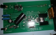
Here are the pictures as promised. I found them on internet and I was pretty shocked!
Note that the heat sink used on the BJT is not even the right one as that is a stand up type of sink, but they threw whatever they had in there to fit the small package size.
Note that the heat sink used on the BJT is not even the right one as that is a stand up type of sink, but they threw whatever they had in there to fit the small package size.
Attachments

Stefanoo,
I believe Pyramid has some plans for DC motors, but I don't want to speak for him. I think we would be lucky to have an engineer of his abilities designing for DIY and it appears he might be going in the direction you are suggesting. My current longer term plan is to follow his path as I believe he has the best near term (AC), long term (DC) design path and being in the U.S. is of course better for me. Pyramid says he will have some new AC controllers around March/April after some parts come in.
How's your Deutsch? If we were able to get Daniel and Pyramid working as an international team we'd have the global dream team of DIY speed controls and motors. I could certainly help with some of the fabrication of pulleys, etc., but these guys are doing all the heavy lifting and I'm curious how to help them, help us.
Jamie
I think we are both saying "rim drive" to mean direct contact by a pulley to the rim of the platter like Thorens TD 124. Stefanoo would like to convert his VPI from belt drive to rim drive and many people believe rim drive or direct drive is better than belt drive.
Schopper AG - Motor & Chassis Restoration
Schopper AG - Motor & Chassis Restoration
When I say RIM drive I am not saying it at the VPI's way, I am actually talking about a pulley driven by the DC motor, directly in contact with the platter.
Stefanoo,
I believe Pyramid has some plans for DC motors, but I don't want to speak for him. I think we would be lucky to have an engineer of his abilities designing for DIY and it appears he might be going in the direction you are suggesting. My current longer term plan is to follow his path as I believe he has the best near term (AC), long term (DC) design path and being in the U.S. is of course better for me. Pyramid says he will have some new AC controllers around March/April after some parts come in.
How's your Deutsch? If we were able to get Daniel and Pyramid working as an international team we'd have the global dream team of DIY speed controls and motors. I could certainly help with some of the fabrication of pulleys, etc., but these guys are doing all the heavy lifting and I'm curious how to help them, help us.
Jamie
I don't speak German. I said all I need to work on this is somebody who can work on the Firmware side, that's all I need. We don't need translators.
Also, if this is got to get done it has to get done now and not in 1, 2 years or I will rather just buy something out (I talk for myself).
So if somebody wants to step in and will work on the Firmware and design concept with me, we could get this started.
I think we have plenty of experienced people here on this forum. Biblio is an expert on motors, the expertise of a persona like this will also add up to the final quality of the project.
Pyramid does this for business, his products are not DIY and to be honest, if he had one for sale now, I would buy it as the AC controller is fantastic IMHO.
So I don't think it is appropriate to ask Pyramid to join us to work for the DIY community, while he does this for a living.
I can do it, because I have a different day job 😱 so I Can work on the spare time and get this done and share it too.
Now I am interest to see if anybody is interested. I know we have potential for a great team work. 😎
DC motor controller
It looks like the OL circuit is just a linear DC regulator. This will provide some stability, but a proper DC motor controller will need to monitor the motor current and provide some a negative resistance feedback as Mark Kelly suggested.
Mark did a very good white paper on the subject in DIYMAG back in 2006. See page 26 on this link:
 Compromised URL removed by Moderation
Don't know how practical (or difficult) it would be to add electronic feedback info via the tach; a properly designed controller should provide stable speed with varying loads. It might just be easier to use the tach to set the idle speed via the trim pot on the controller and let the electronics in the controller keep it on speed.
It looks like the OL circuit is just a linear DC regulator. This will provide some stability, but a proper DC motor controller will need to monitor the motor current and provide some a negative resistance feedback as Mark Kelly suggested.
Mark did a very good white paper on the subject in DIYMAG back in 2006. See page 26 on this link:
Compromised URL removed by ModerationDon't know how practical (or difficult) it would be to add electronic feedback info via the tach; a properly designed controller should provide stable speed with varying loads. It might just be easier to use the tach to set the idle speed via the trim pot on the controller and let the electronics in the controller keep it on speed.
Last edited by a moderator:
then i would suggest that you go DC as it's far far easier to 'trim' the speed. if not then you are going to have to get the pulley very very accurate. plus the added bonus of less mechanical noise in DC motors. one bad point of rim drive is when the mating surface of the pulley wears down the speed accuracy is also affected. to have the facility to 'trim' the speed would be much better as you could check the speed periodically, this is unless you build some sort of tacho that reads the platter speed.
some sort of feedback motor with tacho lock that speaks to the feedback and adjusts automatically.
some sort of feedback motor with tacho lock that speaks to the feedback and adjusts automatically.
that is exactly what I had in mind. With a tachometer, you can lock the speed to the right target even when the rim wears down a little bit.
Either way the o-ring or whatever is used to get in touch with the platter should be changed periodically.
To get the proper speed, trimming the output voltage is the best way rather then getting the pulley extremely precise and like I said with the tachometer, this problem doesn't even exist.
Anyhow, like Pyramid said, it is uncertain whether the closed loop with the tachometer will form a stable system or the speed will start bouncing uncontrollably.
But I think this parameters can be worked out on the actual physical model.
it's all down to the coding and implementation of the sub routine as the feedback will not have to speak to the tacho all the time, say only once when the motor is switched on and the platter is at a stable speed then check, adjust and exit to main code (which will have been adjusted by sub routine). this way the tacho would no be fighting with the feedback during play. all this should only take a matter of seconds when the motor is switched on. i suppose you could add a manual override while playing the record to go into the subroutine so you could adjust for needle drag, but like i have said needle drag is only a problem with light platters and heavy VTF.
While reading, I found an interesting page. I will quote what's in there, it should help understanding a bit more what I am thinking now 🙂
"The power supply has been an area where much time has been spent checking out many alternatives. An initially tempting power supply with motor that includes feedback speed control resulted in rock solid speed stability but it was let down by rumble transmitted to the platter and a strong hum from the controller. Close but no cigar.
A simpler controller with compensation for stylus drag was trialled, whilst this was impressive in resisting pressures even from record cleaning brushes, in the final analysis the sound was spoilt by a smearing of bass notes as the power supply made micro-adjustments to the voltage driving the motor. Simple lead-acid supplies were tested with regulators to govern voltage from the discharging battery. It was soon found that mains powered regulators outperformed the battery once the regulators were suitably configured. So what we have is a linear power supply with multiple cascaded regulators with some extra tweaks that proved to be very important. Cascaded regulators are used to massively filter out mains borne noise helping to ensure the deck performs well at any time of day. Mains power can vary in quality hugely so rejection of noise by the power supply is very important with such a direct drive of the platter.
What is also important to realise is that the power supply purposely makes no attempt to control platter speed other than by supplying a constant voltage. There is no compensation for stylus drag or temperature. Speed does not vary or waiver over short timescales so piano notes for example do not wow. Speed can vary over longer timescales. It takes 10 or 15 minutes for speed to settle at the start of a listening session after which time the speed is usually exactly as it was from the previous day’s listening. Big variations in temperature can require tweaks to the speed setting. Typically I find need to adjust speed after a few days, not normally more frequently than this.
The lack of feedback control for the power supply is a very deliberate design decision which results in improved sound quality. If you are someone who must have a deck which is instantly up to 33.33rpm at switch on and never ever varies from this then I suggest you need a direct drive deck such as a Technics SP10 or 1210. This is “straight-through” analogue with no digital control or feedback mechanisms.
Some final words on the two platter options; the 9kg platter permits the motor to spin a little faster so producing some useful extra torque. Speed is a maintained a little more consistently too as it takes a lot of force to change the speed of a 9kg platter. Any speed drift, even with the acrylic platter, is perfectly acceptable to me and I regard myself slightly on the obsessive side of sane. Speed drift was measured with the acrylic platter to be between 0.3% and 0.6%. The heavy aluminium platter betters 0.3%. The 0.3% figure is regarded in the industry as a standard to achieve. Direct Drives better 0.3% but many others do not. In terms of sound both platters sound great."
Last edited:
DC motor controller
If you are going to run a straight regulator with no current feedback, the firmware would be pretty straight forward. I could probably morph the AC controller OS to do this fairly quickly, as there is no set up for phase or for voltage drop after the platter is running. I think a small pin count µP, E²PROM, a voltage output DAC and some analog circuitry would be all that's needed. If we settle on a design, I can spin the CAD work in a day or less. Let me know if you want me to be involved.
Jamie mentioned my involvement with a DC controller; I was actually looking at a BLDC solution; I don't think I would pursue a DC controller commercially.
Pyramid, sounds great! You are the best team player I could have.
We can take this off line to talk more about details.
I have in mind an extremely low noise/impedance class A power supply.
I don't think though I can get a super low voltage supply with the circuit I have in mind. I think minimum reasonable would be 3-4V, not sure I can find a DC motor that works at a compatible voltage at such a low revs.
If lower supply is needed then I need to re-think the design a bit but it shouldn't be a problem.
Also we should select a motor and have it run at 200-300RPM do it will be compatible with most of the tables around. We don't want to use head gears to reduce speed.
Motor has to have hight torque at that level as well.
I find it fairly easy on my table to test motors. The pulley clears out the outer part of the platter by 3-4mm with the existing pulley.
(I am also going to test the current hurst motor in direct drive config with your controller)
All I have to do is get a 3mm thick (I will get more sizes to get the right tension) silicone o-ring and it should work perfectly.
Although at second thought I don't think that a class a psu is really needed.
Maybe we can talk about this and see what would the best solution be! 😎
Maybe we can talk about this and see what would the best solution be! 😎
Stefano,
I would be happy to help get precision machined parts for ANY motor and PSU you want to build, belt, rim or direct, I don't care. I can't say I know how to make the best belt, rim, or direct drive components, but I'm happy to try my best and get some parts machined. I am sure your ideas and the partners will be good and I'm glad to see, although not surprised at all, that Pyramid would be happy to help with OS and firmware code.
Let's go!
Jamie
Oh, I mean to say I don't know how to design the drive, if I get the components they will be done correctly to high precision. Not sure where to get centerless grinding and honing done right now, but the rest is a piece of cake.
Unfortunately I am an electrical designer and I have no real knowledge on how to get mechanical parts done.
So maybe the help of some other guys to guide you through the design of pulleys and such would be a good idea.
I am finishing up a couple of things this week but next week I can start with Pyramid on the design of the new supply if he is ok with that.
I think we can attempt to make the best DC motor supply.
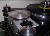
Idea is to get something on the form factor of this in picture (we all know that 🙂 ) but directly powered by the new DC motor system instead of dumb 2 AC motors in flywheel configuration.
Can you get a box like that and a pulley similar to that done? Do you have these capabilities?
As far as dimension you will be provided with all the physical dimension including dimension of box, holes, height, pulley dimension etc etc, but then the design concept has to turn into physical model 🙂
EDIT: the enclosure obviously will be a pod and not a box. But I will shortly post a design idea I have, I would like people to comment on it.
So maybe the help of some other guys to guide you through the design of pulleys and such would be a good idea.
I am finishing up a couple of things this week but next week I can start with Pyramid on the design of the new supply if he is ok with that.
I think we can attempt to make the best DC motor supply.
Idea is to get something on the form factor of this in picture (we all know that 🙂 ) but directly powered by the new DC motor system instead of dumb 2 AC motors in flywheel configuration.
Can you get a box like that and a pulley similar to that done? Do you have these capabilities?
As far as dimension you will be provided with all the physical dimension including dimension of box, holes, height, pulley dimension etc etc, but then the design concept has to turn into physical model 🙂
EDIT: the enclosure obviously will be a pod and not a box. But I will shortly post a design idea I have, I would like people to comment on it.
Attachments
Last edited:
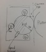
And here is the extended idea (you guys should know that if I engage and start something I will try to do it the best it can get!)
This arrangement should provide more torque, more uniform rotation and less vibration because the pulley in touch with the platter is not in direct contact with the motor.
It will however will be harder to manufacture and a much harder to design a proper control for it (especially a suitable PSU software won't have to change for now...it could get much more fancy and advance from a control standpoint, but I don't think it is necessary for the application).
Attachments
- Status
- Not open for further replies.
- Home
- Source & Line
- Analogue Source
- Hurst AC Motor Let's upgrade it