Hello.
I can confirm this behavior when the amp's input impedance is high.In this mode, after power-on or at any gain change the outputs will swing violently from one power rail to the other for a few seconds until they will begin to sort of stabilize to swings of only a few hundred milivolt amplitudes
I think as the i/p Z gets higher the oscillations get larger. In my instance, anything >= 1K Ohm and the circuit will not stabilize as already mentioned.
So the amp will always oscillate at low frequencies, somewhere below 15Hz. This is a consequence of the DC-coupling and DC- servo.
The DC o/p at the headamp is stable on my amp when it is working correctly. I intend to check this via a scope to see if there is any AC present.
I am currently moving the amp from one small enclosure to a bigger one because of temperature dissipation problems so after rebuilding it i plan on doing some phase margin measurements.
There is quite a lot of heat emitted by the two 100 Ohm resistors (R201) and I have measured temperatures in excess of 90C. Due to the close proximity of the components, in particular C225, these get quite warm, over 60C has been recorded. I have added IC style heat sinks to these 2 Watt resistors to aid dissipation but it's not idea. A more spacious layout is the answer I feel.
If this amp's behavior is a problem to you, you should make sure you use the HFP filter to protect your speakers and if you want you could try to add a few uF of film decoupling capacitor between the first linear amp stage and the filter stage.
I do have the HFP fitted although don't often use it, my amp with a 100 Ohm i/p Z works as expected. I am aware of the very low frequencies which the designer made the HFP to remove (caused by very high low freq. gain and flicker noise) Additionally my TT does not have any rumble which again the HFP would remove.
Another question that was posted by a member was about the amp's sound quality. I have never heard a more detailed phono amp. Sound is crystal clear, no comparison to those muddy op-amp based amps.
When performing correctly, as it has been until I started changing the i/p Z, I concur, the amp is a high end device capable of great detail and dynamics. The RIAA stage is also very accurate, if I recall correctly mine was within +/- .05dBs. And it does of cause have extremely low noise!
I have tested today power supply which I built with schematic values. Regulators output is +/- 21.7V which is safe for RIAA part of preamp.
After PS buffer section there are +/- 18,6V. Both OPA211 and output buffer have max. specified voltage of 18V. Is it safe? What are voltage values of the built preamps?
After PS buffer section there are +/- 18,6V. Both OPA211 and output buffer have max. specified voltage of 18V. Is it safe? What are voltage values of the built preamps?
I have tested today power supply which I built with schematic values. Regulators output is +/- 21.7V which is safe for RIAA part of preamp.
After PS buffer section there are +/- 18,6V. Both OPA211 and output buffer have max. specified voltage of 18V. Is it safe? What are voltage values of the built preamps?
No! This is not safe. Change voltage divider resistors as necessary in order to obtain 17V on the head-amp's rails. Do not go higher than 17V as the rails will drift in time due to temperature affecting both resistors and capacitors. Better safe than sorry
I have tested today power supply which I built with schematic values. Regulators output is +/- 21.7V which is safe for RIAA part of preamp.
After PS buffer section there are +/- 18,6V. Both OPA211 and output buffer have max. specified voltage of 18V. Is it safe? What are voltage values of the built preamps?
The o/p from the regulators is OK (<22Volts). You need to adjust the buffer to give <18 Volts, the designers values will give >18 Volts. Change R418 to a higher value (was 220 ohm now 380 ohm on my amp).
It means that voltage divider 220R/1K8 from schematic is not correct. R 403 and R 412 must be higher.
It means that voltage divider 220R/1K8 from schematic is not correct. R 403 and R 412 must be higher.
The R values will not give <18 volts. Change the 220R as suggested.
This has been discussed earlier in this thread.
Would be nice to hear from others that have working units to compare against.
Yes, this is the reason for my post, but obviously it’s been around for a while and no doubt some of those who built it when it first appeared have moved on.
.The documentation is limited from what I saw, no BOM, no silkscreen/assembly drawings. I do wonder how folks managed to figure it all out.
Being methodical and I personally have worked with SMD so they held no fear for me. I also cut the board on a prototyping mill we have at work. I admit the design has presented something of a challenge (although actually building it, although time consuming, was not difficult). And I have learnt a lot!
I know the designer did not spare any expense. He could have Idss matched all the jfets, made no note of it
Yes, it’s not a cheap design to build but the results are high end. The cost of an equivalent commercial MC phonoamp, who knows? I know of other designs that have benefitted from matching JFets, so maybe this one would too. I don’t have the technical knowledge is say either way. Does having 8 in parallel for example have an averaging effect?
I have spent some time checking/testing my HPS5.1 and have moved forward. Not quite there yet but will post my finding once complete. Looking positive though!
According to designer, J-Fets should be soldered without any sorting and matching. I will not use relays since wire jumpers for changing gain are better solution .
What is the role of R232 resistor? I do not understand relay powering without protecting diodes.
What is the role of R232 resistor? I do not understand relay powering without protecting diodes.
The one I've had suffered from oscillation when the input was left open circuit regardless of the input impedance and was only cured with the reduction of R201 (100R 2W).
There was also a very low frequency drift due to the design sensitivity to temperature and mounting it on a 3mm aluminum plate help.
msdin
There was also a very low frequency drift due to the design sensitivity to temperature and mounting it on a 3mm aluminum plate help.
msdin
Last edited:
According to designer, J-Fets should be soldered without any sorting and matching. I will not use relays since wire jumpers for changing gain are better solution .
What is the role of R232 resistor? I do not understand relay powering without protecting diodes.
An LED is fitted to P203 to indicate the low gain mode is in use. R232 is the current limit for this diode.
Figure out if it is oscillating first. maybe focus on the comp cap, C201
Are the comp caps the right ones, values,type. C201. R206/C206 are interesting.
He shows in his sim drawing, that C201 is 47p, i'd try that, put another 22p on top of the other one,22p?
Well spotted!
I ran a simulation to establish the effects of changing C201, the plot is attached. The values chosen are 10p 22p 33p 47p 64p 88p and the signal is taken at the Headamp output.
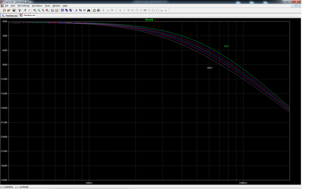
It doesn't vary a great deal, maybe I should be more daring in my component value selection!
The important thing is that there is an HF rolloff. I need to check that the actual amp conforms to the sim now.
You are correct, so I suggest that you do not build this project unless you know how it is designed in the first place.It seems that this is not fully developed project.
I have hand soldered 1000's of MLCC parts, without damaging any. I am not saying that you can not damage them, but you have to be either a butcher if you do or you are using the wrong technique and tools.SMD soldering experts are against soldering SMD multilayer ceramics by hand in the usual manner. They will be damaged, and this is a problem with DIY SMD projects. I adapted leaded MLC to be used here. A few mm of lead absorbs damaging heat.
You are correct, so I suggest that you do not build this project unless you know how it is designed in the first place.
I have hand soldered 1000's of MLCC parts, without damaging any. I am not saying that you can not damage them, but you have to be either a butcher if you do or you are using the wrong technique and tools.
If there is any properly built and working HPS-5.1 then I will take a challenge to build one myself. I have already built and tested PS part of preamp.I have to order OPA827 or find a substitute.
MLCC damage in hand soldering is well known fact described in many scientific works . Simply, they are designed for hot oven soldering.
You are not able to see internal damage by naked eye , one day sooner or later you may have short circuit or loss of capacitance in your eq.Or you are owner of X-ray equipment and tested each soldered sample.
Want to share your ltspice sim and I can follow along.I ran a simulation to establish the effects of changing C201, the plot is attached
Everyone noticed lme49870 is last time buy status, hard to find. OPA604 will work I think, might even be more reliable, been around for a while.
Everyone noticed lme49870 is last time buy status, hard to find. OPA604 will work I think, might even be more reliable, been around for a while.
Farnell UK have a few. And thanks for the heads up 🙂
Further to the issue described earlier, and one I’m not alone in experiencing, I have investigated further with the following results.
Switching the amp on with different input loads and observing the head amp output, the following has been noted –
Z = O ohm. Output swings between +8 and -10 volts at .5Hz with each subsequent cycle diminishing in amplitude. It take 3 cycles, ie 6 secs, for the output to stabilize to around 0V with +/- 2mV AC present. This is the expected behavior.
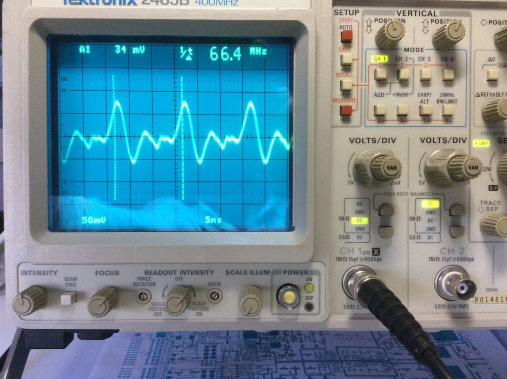
Z = 10 – 1000 Ohms. Although the amp will stabilize as described above, there is a high frequency signal present. This is between 13 and 94 Mhz dependant on the i/p load and its amplitude, which varies for the same reason, is between 10 – 150 mV P-P. The photo below is with the a 10 ohm i/p Z
Z = 47K ohm. The output swings violently between +15/-15Volts and will not stabilize. There is very little time to take any measurements as the high current present is smokin’ the feedback resistors 😱😱
All the above is noted with nothing connected to the i/p and the gain set to high.
So what to do? I have sometimes had radio interference so a possible clue is RF getting into the amp (the 1mH inductors obviously not sufficient to prevent this) I therefore added a 4.7nFcap across the input phono. This not only removed almost all the RF signal but the amp is stable for all i/p load settings at switch on and they can be altered while the amp is powered. The amount of RF now present at the head amp o/p is .8mV @ 73 MHz (load @ 47K).
I have looked further into the impact of adding the capacitor, ideally I would have preferred a lower value but the one used is needed. More to come……………….
Switching the amp on with different input loads and observing the head amp output, the following has been noted –
Z = O ohm. Output swings between +8 and -10 volts at .5Hz with each subsequent cycle diminishing in amplitude. It take 3 cycles, ie 6 secs, for the output to stabilize to around 0V with +/- 2mV AC present. This is the expected behavior.
Z = 10 – 1000 Ohms. Although the amp will stabilize as described above, there is a high frequency signal present. This is between 13 and 94 Mhz dependant on the i/p load and its amplitude, which varies for the same reason, is between 10 – 150 mV P-P. The photo below is with the a 10 ohm i/p Z
Z = 47K ohm. The output swings violently between +15/-15Volts and will not stabilize. There is very little time to take any measurements as the high current present is smokin’ the feedback resistors 😱😱
All the above is noted with nothing connected to the i/p and the gain set to high.
So what to do? I have sometimes had radio interference so a possible clue is RF getting into the amp (the 1mH inductors obviously not sufficient to prevent this) I therefore added a 4.7nFcap across the input phono. This not only removed almost all the RF signal but the amp is stable for all i/p load settings at switch on and they can be altered while the amp is powered. The amount of RF now present at the head amp o/p is .8mV @ 73 MHz (load @ 47K).
I have looked further into the impact of adding the capacitor, ideally I would have preferred a lower value but the one used is needed. More to come……………….
Further to the issue described earlier, and one I’m not alone in experiencing, I have investigated further with the following results.
Switching the amp on with different input loads and observing the head amp output, the following has been noted –
Z = O ohm. Output swings between +8 and -10 volts at .5Hz with each subsequent cycle diminishing in amplitude. It take 3 cycles, ie 6 secs, for the output to stabilize to around 0V with +/- 2mV AC present. This is the expected behavior.
Z = 10 – 1000 Ohms. Although the amp will stabilize as described above, there is a high frequency signal present. This is between 13 and 94 Mhz dependant on the i/p load and its amplitude, which varies for the same reason, is between 10 – 150 mV P-P. The photo below is with the a 10 ohm i/p Z
Z = 47K ohm. The output swings violently between +15/-15Volts and will not stabilize. There is very little time to take any measurements as the high current present is smokin’ the feedback resistors 😱😱
All the above is noted with nothing connected to the i/p and the gain set to high.
If Z is the source impedance, then what would be the point of connecting such at the input? Set aside the reactive part (inductance) is a great RF collector, anything over 10ohm (resistive) exceeds the noise of the amp itself.
I believe 4.7nF at the input is a big nono for a MM cartridge, it will resonate in the audio band with the MM cartridge high inductance.
I bought in a local store 1008 SMT package 1 micro inductors declared as ceramic core. But they are attracted to magnet so I think that core are ferrite.
Soldering pads on PCB are for 1210 package but at Mouser I was not able to find any similar to original HPS 5.1 picture. What would happen with magnetic core inductors in circuit?
Fasterbyelan, what input inductors do you use?
Soldering pads on PCB are for 1210 package but at Mouser I was not able to find any similar to original HPS 5.1 picture. What would happen with magnetic core inductors in circuit?
Fasterbyelan, what input inductors do you use?
If Z is the source impedance, then what would be the point of connecting such at the input? Set aside the reactive part (inductance) is a great RF collector, anything over 10ohm (resistive) exceeds the noise of the amp itself.
I believe 4.7nF at the input is a big nono for a MM cartridge, it will resonate in the audio band with the MM cartridge high inductance.
Z is the input resistance of the amplifier ie the cartridge load - apologies if this was misleading.
Yes I agree that 4.7nF would not work with a MM cartridge with its higher inductance. I'm trying to get my amplifier to behave properly with the cartridges I own which are all MC type - the solution is working. The only caveat is when using the SUT which I'm yet to try. I'm not sure what effect the capacitor will have in this instance (what inductance does the amplifier i/p see for example?).
For those who know the circuit, would increasing the inductor size on the FET inputs be a possible solution to the RF interference problem?
- Home
- Source & Line
- Analogue Source
- Hps 5.1