I did but it is long gone, with my ex wife and the computer. I did share it with a few other builders, hopefully they still have it.
Thanks for letting me know. I will probably raise one anyway as it's good practise and will give me a better understanding of what's required.
Cheers,
Karl
A question for HPS-5.1 builders : Which type, brand and cat. no. of input fets gate inductors do you use?
Last edited:
HPS 5.1 designer recommended air cored inductors for L201-L208. I am unable to find ferite-free SMD inductors of such a small value. That was the reason I asked for help , but forum members are probably too busy with their soldering irons.A question for HPS-5.1 builders : Which type, brand and cat. no. of input fets gate inductors do you use?
Maybe something like this (coil wound on ceramic core):
MULTICOMP|MCWL06KT1R0|INDUCTOR, 1000NH, 320MA, 10%, | Farnell United Kingdom
Regards,
George
MULTICOMP|MCWL06KT1R0|INDUCTOR, 1000NH, 320MA, 10%, | Farnell United Kingdom
Regards,
George
Thank you very much, that is what I tried to find.Maybe something like this (coil wound on ceramic core):
MULTICOMP|MCWL06KT1R0|INDUCTOR, 1000NH, 320MA, 10%, | Farnell United Kingdom
Regards,
George
This looks suitable as well and does not incur the US stock additional charge the Farnell part does - Buy Inductor Surface Mount 1008 WL Series SMT inductor, 1uH ATC 1008WL102J online from RS for next day delivery.
It's the next size down (1006) but seems to fit the PCB OK (soldering skills dependant!)
Karl
It's the next size down (1006) but seems to fit the PCB OK (soldering skills dependant!)
Karl
Well I have moved forward.
I have the PCB's for the amp and rumble filter. The price for the components is around £400 - does this sound around right ?
Has anyone built the circuit and noted any of the DC voltages present. I have been trying to calculate values within the head amp but things don't work out (probably due to my limited knowledge
 )
)
Cheers,
Karl
I have the PCB's for the amp and rumble filter. The price for the components is around £400 - does this sound around right ?
Has anyone built the circuit and noted any of the DC voltages present. I have been trying to calculate values within the head amp but things don't work out
(probably due to my limited knowledge)Cheers,
Karl
Well I have moved forward.
I have the PCB's for the amp and rumble filter. The price for the components is around £400 - does this sound around right ?
Has anyone built the circuit and noted any of the DC voltages present. I have been trying to calculate values within the head amp but things don't work out (probably due to my limited knowledge)
Cheers,
Karl
I have the PCB's for the amp and rumble filter. The price for the components is around £400 - does this sound around right ?
Has anyone built the circuit and noted any of the DC voltages present. I have been trying to calculate values within the head amp but things don't work out
(probably due to my limited knowledge)Cheers,
Karl
Maybe a tad more than i spent but probably about correct. The fact that SMD part are dearer than thru hole doesnt help
Maybe a tad more than i spent but probably about correct. The fact that SMD part are dearer than thru hole doesnt help
Thanks - I have had to buy more parts than required due to the minimum quantities although I will have nearly enough parts to make another head amp. If the amp works out I may make a remote head amp located at the tone arm end of things.
Now where's my credit card...............
Karl
The MOQ is a bitch, best of luck with it Karl.
Agreed😉
Now that I have the components, I have cracked on with the build as below –
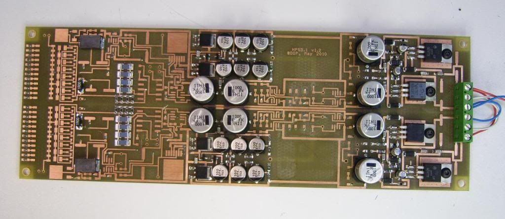
All the power regulator parts are fitted and load regulation tested. I have a number of quires.
1. The VCCL rails have poor regulation (1.5 % no load/ .7 A load). Could this be a circuit layout issue as building the circuit off the board gives < .1% load regulation (I have checked the build and removed non-critical components to no avail)? The unloaded o/p voltage is correct to the calculated value (21.55V).
2. Both VDDL rails are higher than the calculated values at -22V. Regulation is .1%
3. Although they meets with the calculated value through the Sziklay pair, all the head amp supplies are too high (2.7 V below the regulator o/p’s off load – 18.8V typically) . The op amps in the head amp have a maximum voltage of +/- 18 V.
Whilst a little concerned about the poor regulation of the + rail, the total voltage swing of the +/-regulator o/p’s is within the spec of the RIAA stage op amps (LME49870 - 46V). The head amp supplies need adjusting and replacing R403/12 with 374 ohm (from 220 ohm) should give around 17.7 V.
Have others come across these issues or am I doing something wrong ? Feedback would be grateful. For info I am using .1% resistors and powering the board from a dual power supply.
Thanks and a belated Happy New Year!
Karl
Last edited:
@fasterbyelan
I had the same concerns and also modified the voltage divider resistors as you said, to have a voltage drop of below 18 volt for OPA211.
Interesting ideea to fit THD versions of LM317/LM337. It seems that onlt TI's regualtors have three terminals plus heatsink. I had to solder the middle terminal to the board with extension wire.
Finally
Hi Guys,
I am finally putting my HPS5.1 together and wondering what raw voltage power/transformers and what the final raw rail voltage was used for both the 5.1 and the rumble filter. I see that a raw PS used in the 4.1 was 22v transformers. I was looking to build the same with one additional PS for the rumble filter.
Your help would be greatly appreciated.
Cheers
Greg
Do the math for the LM317 (U401) with the values shown
R406[4k] / R401[250] +1 * 1.25 = 21.25V = wrong
In this ckt, I use 2k61 for R406 & 237 for R401 = 15.016V
Regulation issues are related to:
In this case, possibly Vin - Vout differential issue? Coming out of regulation!!
Mostly lack of where the sense point is for the regulator and IR losses in your wiring
As much as I admire what syn08 put forth, you still have to question/reason why things are the way they are documented and do a sanity check on things.
He has done his work in ORCAD, so doing a pspice sim of the ckt would not hurt
syn08 is no where to be found to answer ? of his design. I think he got pissed off, the clash of the strong headed EE on this site.
I was lucky enough to have downloaded his
file:///C:/Projects/DIYAudio-LowNoiseDesigns/LNschematics.html
the link was broken last time I looked
Hint, if you see something out of wack, especially supply voltages, shut it down immediately, investigate. Always check your power supplies first before powering up the loads.
Maybe so, if you have scr crowbar ckt for faults. In this case I use a 2N6395 SCR triggered by a 1N5246A zener. They use this ckt in expensive test equipment, thanks HP. The last thing you want is a supply rail to fail short and fry 1000's of $ of parts/time down stream. All for the cost of less than a 1$ of parts. I just read at audiokarma.org site that a guy lost his AM/FM tuner in a SX-1980, because the 13.5V rail pass transistor shorted out. The few special Pioneer IC's in the ckt are very hard to find.
Keep posting on your progress.
Last edited:
As much as I admire what syn08 put forth, you still have to question/reason why things are the way they are documented and do a sanity check on things.
syn08 is no where to be found to answer ? of his design. I think he got pissed off, the clash of the strong headed EE on this site.
Yes, he had interesting projects, and a very short fuse, unfortunately. Asking certain questions or doubting any part of his designs was a big no-no. How dare we lowly mortals. Too bad, really.
I recall a remark that Scott Worcer made, on this design, all this for a piece of synthetic diamond scratching some plastic. None the less, these designs are an inspiration to me at least.
I was looking at a Sansui CA-F1 pre-amp design lately, it uses 6x 2sk163 & 6x 2sj144 in the MM head amp.You can get the schematic from www.hiengine.com
Rick
I was looking at a Sansui CA-F1 pre-amp design lately, it uses 6x 2sk163 & 6x 2sj144 in the MM head amp.You can get the schematic from www.hiengine.com
Rick
- Home
- Source & Line
- Analogue Source
- Hps 5.1