Ha, that is the perfect solution. The hum breaker bulb. Lights up to let you know you have a ground fault. Although you still need to protect input circuits from excessive voltage and ESD.
Last edited:
I think this shows where I am coming from. R4 represents the connection between the two grounds.
Ok - got it.
Do you think the 0V connection between the PSU and the amp module is in the feedback loop?
Looks like that to me. It's an error that is corrected by the (op)amp, like any other Voltage applied to the output.
x
I do agree, from 0V on the amp board would have a shorter route to speaker return, I did it this way because the lower noise.
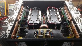
Bonsai, this is how I did it. Two wires going from 0V psu, one to 0V on amp board and the other to speaker return. These slewmaster input modules do have a HBR resistor with the two diodes. The amp is very quiet, no buzz or hiss with inputs shorted. As quiet as a mouse with slippers on a wool carpet.🙂Do you mean the 0V at the PSU or on the amp module?
If it’s the 0V back on the amp module, then yes you are correct. But, Ilimzn shows how to mitigate this clearly (and its in my slides in the HBR section). If you take the speaker return back to the PSU 0V your loop areas are significantly larger. And you will still have the induced loop current problem to deal with either way - and it’s as serious a problem as the common impedance one you are alluding to.
You have to keep the 0 V to the amp modules short and thick.
I do agree, from 0V on the amp board would have a shorter route to speaker return, I did it this way because the lower noise.
Attachments
Last edited:
Wow, nice looking build there Vrystaat!
If you connect a cable across the two channels ( so plug one end in on channel and the other end of the same cable into the other channel is it still quiet? This is a simple test for a cross channel ground loop.
If it gets more noisy you then have to work out if it’s common impedance coupling or mag field loop currents.
Looks like that to me. It's an error that is corrected by the (op)amp, like any other Voltage applied to the output.
I don’t think it’s in the feedback loop. Stuff to the left of the feedback network up until the lower gain setting resistor connection to 0 V is in the loop - everything to the right is outside the loop.
The 0V connection to the speaker as you show it is in series with the load but no in the loop.
If you modulated the ground resistance, I would expect distortion to go up.
Last edited:
Looks like that to me. It's an error that is corrected by the (op)amp, like any other Voltage applied to the output.
The amp can only correct error voltages that are developed inside the loop. R4 is outside the loop. The amplifier will develop a low-distortion signal across the series combination of the loudspeaker and R4. But crud from the amplifier decoupling caps will flow through R4, developing a distorted voltage signal across R4. If the sum of the voltage across R4 and the loudspeaker is non-distorted, but the voltage across R4 is distorted, the voltage across the loudspeaker will necessarily also be distorted - it's the only way that V(R4) and V(Loudspeaker) can sum to a non-distorted waveform.
Why not use just one HBR?So with those responses it appears the consensus is basically that it's so unlikely that the RCA barrels will ever see an internal 120V fault that it's not considered a significant risk.
Well well, that is great, a fellow South African !😀I’m originally from Durban
The amp can only correct error voltages that are developed inside the loop. R4 is outside the loop. The amplifier will develop a low-distortion signal across the series combination of the loudspeaker and R4. But crud from the amplifier decoupling caps will flow through R4, developing a distorted voltage signal across R4. If the sum of the voltage across R4 and the loudspeaker is non-distorted, but the voltage across R4 is distorted, the voltage across the loudspeaker will necessarily also be distorted - it's the only way that V(R4) and V(Loudspeaker) can sum to a non-distorted waveform.
R4 is in the FB loop, compare it to back EMF or biassing the output to force the amp into class A. I'll post some simulations later.
I think this shows where I am coming from. R4 represents the connection between the two grounds.
In this layout the amp return current must flow through the onboard caps and then the hum breaker to get back to the speaker. This will cause massive noise issues and a severe input ground loop.
EDIT: I guess you are just illustrating the resistance of the umbilical 0V?
Last edited:
In this layout the amp return current must flow through the onboard caps and then the hum breaker to get back to the speaker. This will cause massive noise issues and a severe input ground loop.
Sorry, I do not see what you see.
R4 is the 0V connection between the amp module and the PSU.
Mark has not shown an HBR - his question is focused on the speaker retuen wire placement.
Am I missing something here?
I have seen the layout same as Mark but there is no local decoupling capacitors and R4 is not significant, near as zero (placing close as 0V on power supply, a design which integrates power supply into amplifier board)
Regarding Bonsai's layout.
Having speaker return on the amp board with signal return minimizes the return current the earth loop shares with the PSU, but does not change the fact that they share a conductor. This may be a good compromise for channels that share a PSU, but the power supply return currents still share a conductor with the earth loop and therefore if this layout is to be improved (regardless of whether you think that's necessary), that conductor sharing must be eliminated.
But, why don't we talk about loop areas as that is another route of improvement.
If, in Bonsai's layout, it is loop areas and magnetic induction that limits performance instead of the shared conductor, then what would be the areas to improve?
R4 is in the FB loop
No, it is not. For the avoidance of doubt, I am talking about the image you posted in post #119. The feedback voltage is derived from the R2, R3 potential divider. Negative feedback will cause the voltage developed at the amp's "-" input to track that of the "+" input, the reference node being the one you have labelled "Amp 0V".
As I said, the amplifier will develop a low-distortion waveform across the series combination of the loudspeaker and R4.
Look at it another way: take your diagram and delete R4 (don't replace it with anything - just delete it). Is there still a feedback loop? Answer - yes. Therefore R4 is not inside the loop. However, now current cannot flow in the loudspeaker as there is no return path back to the amplifier. So connect R4 again - it is part of the load, not the feedback loop.
- Home
- Amplifiers
- Solid State
- How to wire up an Amplifier