My take is that if your amplifier is safely earthed (grounded) you still cannot expect it to proved a safety ground for piece of faulty equipment that’s is connected to it.
Each piece of equipment must be completely safe in its own right.
HBR issue solved.
Each piece of equipment must be completely safe in its own right.
HBR issue solved.
When using a 1 or 10 ohm HBR on the amplifier PCB, what sort of construction and power ratings are recommended? Wirewound? Metal film? MOX? 1/4 watt, 1 watt, 3 watt or more?
Thanks all. Brilliant thread!
Thanks all. Brilliant thread!
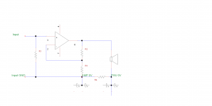
That is what I have done. If you limit the voltage over the HBR to about 1V with the diodes, it will prevent a 1ohm 1/4 W resistor from going open in the case of a current spike that can happen when connecting equipment together. In my opinion, the HBR is not a safety problem when used in an audio amp. Different story for an instrument amp where the input ground is connected to the instrument.
If the HBR fails and the feedback loop is broken, the amp will go open loop with full negative rail on the output.
If the HBR fails and the feedback loop is broken, the amp will go open loop with full negative rail on the output.
Last edited:
That is what I have done. If you limit the voltage over the HBR to about 1V with the diodes, it will prevent a 1ohm 1/4 W resistor from going open in the case of a current spike that can happen when connecting equipment together. In my opinion, the HBR is not a safety problem when used in an audio amp. Different story for an instrument amp where the input ground is connected to the instrument.
If the HBR fails and the feedback loop is broken, the amp will go open loop with full negative rail on the output.
This is a good trick - I've had a 3.3 Ohm 0.25W HBR go open circuit and back to back diodes like this would have probably saved the resistor.
So with those responses it appears the consensus is basically that it's so unlikely that the RCA barrels will ever see an internal 120V fault that it's not considered a significant risk.
I see the implementation .... There are two diodes in parallel with the resistor. One diode is reversed. One will conduct when the absolute value of the voltage on the signal ground is greater than the forward voltage drop. So,there is no protection for anything other than the HBR -- they represent a bypass.
I suppose this adds bulk to the HBR "system" thus raising the challenge level for those who are retrofitting.I see the implementation .... There are two diodes in parallel with the resistor. One diode is reversed. One will conduct when the absolute value of the voltage on the signal ground is greater than the forward voltage drop. So,there is no protection for anything other than the HBR -- they represent a bypass.
Even if you bolt the RCA on to the chassis. Do you expect the PCB traces between power and input to withstand high currents?
I've added ilimzn's excellent posts 50 and 51 to the first post in this thread - his explanation and the HBR/loop area minimization is clear and concise.
What I do remember when building a Slewmaster amp. Thimios did noise tests of which is best by connecting the speaker return to the amp pcb or to the 0V of the power supply. He tested the amp much more quiet with speaker return at the 0 point. It is obviously much easier from the amp pcb because the output wires run together, but that is what he has proved with shown measurements. Whether there is a difference between dual mono or with only one transformer for both channels, that I can not say. Thimios, If you read this, can you plse help.
Last edited:
What thoughts are there on these posts of ilimzn's?
https://www.diyaudio.com/forums/solid-state/324413-dozens-schemes-wire-amp-4.html#post5477189
https://www.diyaudio.com/forums/solid-state/324413-dozens-schemes-wire-amp-5.html#post5477333
https://www.diyaudio.com/forums/solid-state/324413-dozens-schemes-wire-amp-4.html#post5477189
https://www.diyaudio.com/forums/solid-state/324413-dozens-schemes-wire-amp-5.html#post5477333
Vrystaat,
If you take the speaker return back to the PCB, you have to use a HBR on your amp modules to reduce the loop current in the input wiring. Secondly, if you have not placed your input connectors next to each other and bonded them together, you will be very susceptible to noise pickup from radiated field from the transformer inside the amp.
The benefit of taking the speaker return back to the amp module 0V is you minimize the loop area of the speaker wiring inside the amp - you don't want to be radiating potentially large signal related magnetic fields inside the amp.
I've also done measurements and gotten a better result taking the speaker return back to the PCB rather than the PSU 0V common - so, the point is which one works best is very implementation dependent.
Bonsai, connecting speaker return to 0V means that the currents between 0V and amp ground are modulating the output as this connection is in series with the load. Something that would be hard to measure as it would be corrected/removed by the feedback.
Do you mean the 0V at the PSU or on the amp module?
If it’s the 0V back on the amp module, then yes you are correct. But, Ilimzn shows how to mitigate this clearly (and its in my slides in the HBR section). If you take the speaker return back to the PSU 0V your loop areas are significantly larger. And you will still have the induced loop current problem to deal with either way - and it’s as serious a problem as the common impedance one you are alluding to.
You have to keep the 0 V to the amp modules short and thick.
Last edited:
I see the implementation .... There are two diodes in parallel with the resistor. One diode is reversed. One will conduct when the absolute value of the voltage on the signal ground is greater than the forward voltage drop. So,there is no protection for anything other than the HBR -- they represent a bypass.
The hum breaker resistor doesn't need to be delicate, it could be a stick of graphite glowing red hot as the linearity doesn't matter at all. Carbon comp has very high surge ability, I wonder if there is anything better?
Bonsai, not really, in that example, the input is modulated. I am talking about the voltage between PSU and amp being in series with the load when the load return is connected to the PSU. I'll see if I can find a schematic to demonstrate this better.
The hum breaker resistor doesn't need to be delicate, it could be a stick of graphite glowing red hot as the linearity doesn't matter at all. Carbon comp has very high surge ability, I wonder if there is anything better?
Light bulb?
- Home
- Amplifiers
- Solid State
- How to wire up an Amplifier