But if you don't use more than a few watts from your tube amp, you may never see more than 6V at the output.
Come to think of it, you could just use the trimmers on the NX3000D and nothing else. (I'm assuming it has some)
Come to think of it, you could just use the trimmers on the NX3000D and nothing else. (I'm assuming it has some)
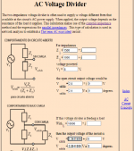
I had forgotten this .......😉 ( thanks rayma, perfect ! Behringer and other manufacturers have standardized 0.750 Volts to 0 dB, I think it will work , the DC calculator says that:
.....................
It should say 0.775 Volts, my mistake.
38 watts into 8 ohms is 16V.
Just to comment on the online calculators, which are very useful, would be exact 17.44 Volts .....
Calculadora de la ley de Ohm | Inventable
> Behringer ........ standardized 0.775 Volts to 0 dB,.....................
0.775V goes back WAY before Behringer was born.
0.775V in 600 Ohms is 1 milli-Watt. Much gear from the late 1930s through the 1960s was calibrated for 600 ohm loads.
0.775V goes back WAY before Behringer was born.
0.775V in 600 Ohms is 1 milli-Watt. Much gear from the late 1930s through the 1960s was calibrated for 600 ohm loads.
Ok, thanks for the info. Likewise, I said "and many other brands", repeating like a parrot what was said by another member.
The following is on my own:
1 Volt output was the "standard" adopted when the CDA came out, there I think there were no disagreements.
At least, it never happened to me that a CDA player doesn't work properly on an AUX input of any SS amplifier.
Where the theory ended, (quite rusty due to lack of use, but I am gaining knowledge now that I am retired and I can dedicate myself "full time" to my passion, audio) is with the adaptation of microphone impedances.
I will open a specific thread with my problem, I hope I can clarify my doubts.
Greetings Prr
But if you don't use more than a few watts from your tube amp, you may never see more than 6V at the output.
Come to think of it, you could just use the trimmers on the NX3000D and nothing else. (I'm assuming it has some)
The amp is new, so I won't open - to look for trimmers inside - because it would lose the warranty.
Equal grace for the suggestion.
Thank you for your valuable contribution.
Attachments
Last edited:
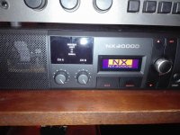
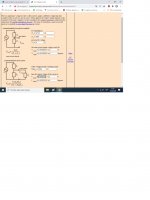
I have finished building the voltage divider and tested it with the tube amp.
With the potentiometers of the Bheringer NX3000D amplifier at maximum, the green light barely blinks (minimum gain, although the crossover was chosen between 20 to 60 hz with the DSP) The basic display of the same is not very intuitive, but once the you learn, it works great!
And there will be time to download and experiment with the software.
So I went to a new calculation, this time to achieve a voltage of more than 2 volts, because 1 volt being the typical output of a CD player, the red displays did not blink applying a very high SPL level of bass.
I leave you the calculations with which I will test tomorrow.
Attachments
You may need another transformer for ground isolation, depending on gain and signal levels. 1:1 or step-down, and keep it far from any power transformers...
Tombavis :
I do not understand what you mean. Can you explain why you say it?
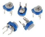
I have decided to try a 10 Kohms (linear) potentiometer for each channel, in replacement of Z1, so I can regulate to the optimum level. Tomorrow I will buy the same ones, I will put on a chinstrap and protective mask and I will go out to expose my life to Covid-19.
It is a difficult world that we have to live in, some people did not understand the importance of taking measures on time, and they ignored responsible advice...
I do not understand what you mean. Can you explain why you say it?
I have decided to try a 10 Kohms (linear) potentiometer for each channel, in replacement of Z1, so I can regulate to the optimum level. Tomorrow I will buy the same ones, I will put on a chinstrap and protective mask and I will go out to expose my life to Covid-19.
It is a difficult world that we have to live in, some people did not understand the importance of taking measures on time, and they ignored responsible advice...
Did you get the Circulation Permit?
You won´t be able to drive or use Public Transport if not, limiting you to buy components locally.
You won´t be able to drive or use Public Transport if not, limiting you to buy components locally.

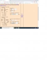
I have finished building the voltage divider and tested it with the tube amp.
With the potentiometers of the Bheringer NX3000D amplifier at maximum, the green light barely blinks (minimum gain, although the crossover was chosen between 20 to 60 hz with the DSP)
Pics and resistors used in failure.
17.44 Volts are for maximum power, that's wrong.
So I will use 6 volts of average and adjustable potentiometers to adjust to taste, much more practical. How did it not occur to us before ?
Attachments

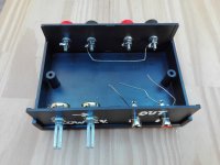
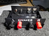
Can you believe that I had to make two visits to the electronics parts house ? 😡
The potentiometers marked 10,000 ohms had 10300 and 8600 ohms, too much of a difference, so i asked to change them, i got a difference between both of only 400 ohms ...😉
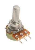
It was a bit difficult to cut the splined shafts, and I used a spell checker to paint the letters ...
Yes, awful !
But it will be hidden, it will not be seen ...😀
The potentiometers marked 10,000 ohms had 10300 and 8600 ohms, too much of a difference, so i asked to change them, i got a difference between both of only 400 ohms ...😉
It was a bit difficult to cut the splined shafts, and I used a spell checker to paint the letters ...
Yes, awful !
But it will be hidden, it will not be seen ...😀

- Home
- Amplifiers
- Tubes / Valves
- How to take low level signal from an OPT ?