it may be easier to take audio at low impedance from some cathode follower adding a 47Ω in series with any amplifier inside the amp, from the bypass cap to ground, and taking out audio across this resistor. Then you avoid last stage (Power) distortion.
Look at post 12, you must read the whole thread, you are being "pedaling in the air" very often, friend.......😀
" The PL weighs 30 KG, manipulating it is complicated. I could take a signal from the potentiometer, and place an RCA token somewhere on the back panel, but that would ruin it and ruin its resale value. I don't plan to change it, but you never know ....."
In addition, if it were and intervene within the amplifier, the simplest is to take a variable signal from the volume potentiometer. To do what you say, there is the monitor output (it is a fixed level, it does not work for me)
Last edited:
Pure subwoofer front plate low pass filter high level input DIY pre tone balanced input / output board-in Switch Caps from Home Improvement on AliExpress
Other :
SUBWOOFER LOW-PASS FILTER Front Plate + High Level Input (input output balance) - $15.67 | PicClick
This looks too much like the board used by the Dayton SPA250, I think that is what I need ....
But it is monophonic output, so I would have to get a plate for each channel, any observations?
Other :
SUBWOOFER LOW-PASS FILTER Front Plate + High Level Input (input output balance) - $15.67 | PicClick
This looks too much like the board used by the Dayton SPA250, I think that is what I need ....
But it is monophonic output, so I would have to get a plate for each channel, any observations?
Last edited:
" Current buffer
Typically a current buffer amplifier is used to transfer a current from a first circuit, having a low output impedance level, to a second circuit with a high input impedance level.[1] The interposed buffer amplifier prevents the second circuit from loading the first circuit's current unacceptably and interfering with its desired operation. In the ideal current buffer in the diagram, the output impedance is infinite (an ideal current source) and the input impedance is zero (a short circuit). Again, other properties of the ideal buffer are: perfect linearity, regardless of signal amplitudes; and instant output response, regardless of the speed of the input signal. "
Buffer amplifier - Wikipedia
According to the above statement, the PCB of the previous link would be a current buffer.
I insist on this issue because I have had serious doubts if a simple resistive divider would be what I need.
Let us not forget that the output impedance of the secondary winding of the valve amplifier (4 or 8 ohms) will be in parallel with the voltage divider and then it will be modified.
Could it affect you FR? More distortion?
I think I need something more "elaborate" as the Wikipedia article suggests, but in my case I would not need the high pass filter or phase inverters, or gain selectors, nor a crossover frequency selector. All this will be done by the Bheringer NX3000D, through DSP.
I found that this amplifier has an input sensitivity of 0.775 Volt / 4 ohms for maximum power.
Therefore, I think it would be better to adapt the impedance with a current buffer like the one mentioned above and then place a resistor in series until the signal is attenuated to the required value.
What do experts say here ?
PS: Maybe someone can facilitate some simple circuit .....😉
academia₅₀;6039940 said:… Therefore, I think it would be better to adapt the impedance with a current buffer like the one mentioned above and then place a resistor in series until the signal is attenuated to the required value.
What do experts say here ?
PS: Maybe someone can facilitate some simple circuit .....😉
0.775 VRMS into 4 Ω? Ah, that cannot be right for a power amplifier. The value "0.775 V" has a very, very specific application, and that is what the reference voltage is, into a 600 Ω "microphone" preamp input, or between stages. It is a remarkably unique number, in audio. Basically, it is exactly 1 milliwatt of power into a 600 Ω load. Using the formulæ
№ 1: E = I R … Ohm's Law, volts equals current times resistance
№ 2: P = I E … Power Law, power (watts) equals current times voltage
We can use a tiny bit of high-school algebra to combine these into the needed equations№ 2: P = I E … Power Law, power (watts) equals current times voltage
E = I R, solving for I
I = E/R, now using in P = E I
P = E (E/R), and combining
P = E²/R
which now we'll use with 1 milliwatt, and 600 ΩI = E/R, now using in P = E I
P = E (E/R), and combining
P = E²/R
P = E²/R
(0.001 W = 1 mW) = E² ÷ 600 Ω
E² = 0.001 W × 600 Ω
E² = 0.600
E = √(0.600)
E = 0.774597 VRMS
So, there's the magic number. Now, the audio trade has long standardized on this value as “0 dBu”, where the 'u' bit at the end denotes 0.775 V as the “zero dB” level of a line signal. (0.001 W = 1 mW) = E² ÷ 600 Ω
E² = 0.001 W × 600 Ω
E² = 0.600
E = √(0.600)
E = 0.774597 VRMS
Anyway, tho' you've gotten a lot of us to debate the various merits of how to tap-the-output-transformer for a signal, there is NO FINER TAP than a quality fixed-resistor-ladder divider. It does the job, and it presents a quite-low (good) output impedance to drive whatever sub-woofer amplifier or speaker system you desire.
REMEMBER, a low impedance source can always accurately drive a low-to-mid-to-high impedance input.
But a high impedance source can not drive a low or mid impedance input. … period …
Repeat that last reminder to yourself a few times until it makes sense. The output impedance gives a specification of just how much current (and effectively, power) can be delivered to 'outside the unit'. The input impedance likewise gives specification for how much, or little current (and power) is required to adequately and accurately receive a signal.
Matching them exactly is rarely of any value, at audio frequencies.
So, as was said MUCH earlier in this thread, a resistive voltage divider on the 8 Ω, or 4 Ω output is going to deliver exactly what you need, for subwoofer inputs.
Anyway, dig into the INPUT requirements (not the fake ones, or 'believed' ones, but actual specs!!!) of the subwoofer system; take whatever is given to be the input impedance, and divide by 10. Then, take the full 'reasonable power' of your amplifier (which you'll be tapping), and work it all backwards, mathematically. Just as I did before.
RHI = ( 1 / attenuation - 1 ) • RLO
RLO approximately equals the 'divide-by–10' impedance
attenuation = 0.775 V / √(PAMP × 4 Ω)
As in this example:RLO approximately equals the 'divide-by–10' impedance
attenuation = 0.775 V / √(PAMP × 4 Ω)
PAMP = 100 W
attenuation = 0.775 V / √(100 × 4)
attenuation = 0.775 ÷ 20
attenuation = 0.0387
target impedance is 10,000 Ω … divided by 10 = 1,000 Ω, SOattenuation = 0.775 V / √(100 × 4)
attenuation = 0.775 ÷ 20
attenuation = 0.0387
RLO ≈ 1,000 Ω
RHI ≈ (( 1 / attenuation ) - 1 ) • RLO
RHI ≈ (( 1 ÷ 0.0387 ) - 1 ) × 1,000 Ω
RHI ≈ 24,820 Ω
Which we can safely round to either 22 kΩ, 24 kΩ, 25 kΩ or even 27 kΩ. The exact value isn't as important as the proportional relationship to the RLO. RHI ≈ (( 1 / attenuation ) - 1 ) • RLO
RHI ≈ (( 1 ÷ 0.0387 ) - 1 ) × 1,000 Ω
RHI ≈ 24,820 Ω
I sincerely hope you got that! I really do.
Anyway, you have a bunch of fuel for the fire.
⋅-⋅-⋅ Just saying, ⋅-⋅-⋅
⋅-=≡ GoatGuy ✓ ≡=-⋅
Last edited:
CabraGuy :
Too many calculations to answer now, but I appreciate your intention and your calculations, they are much appreciated.
With time (now it's almost midnight here) I will give you the information of why that is the voltage of the input signal that Bheringer specifies. It does not say the input impedance.
But remember that it is not a conventional amplifier but an amplifier with switched source, class D, with built-in DSP.
Thanks again
academia₅₀;6040049 said:CabraGuy :
Too many calculations to answer now, but I appreciate your intention and your calculations, they are much appreciated.
With time (now it's almost midnight here) I will give you the information of why that is the voltage of the input signal that Bheringer specifies. It does not say the input impedance.
But remember that it is not a conventional amplifier but an amplifier with switched source, class D, with built-in DSP.
Thanks again
Sure. I suggest you just give me the model number …, so that I can look up the parameters, definitively, myself. From there, I'll be able to give you a perfect pair of resistor values that will be (1) easy to acquire, (2) deliciously LOW noise, (3) able to handle your power-amplifier's output power, and (4) too-easy-to-be-true implementation.
Looking forward to hear back from you, Sir.
⋅-=≡ GoatGuy ✓ ≡=-⋅
Hi friend, this is the only thing I could find, please look at page 40
https://www.parts-express.com/pedocs/manuals/248-7013--Behringer-NX3000D-Manual.pdf
But there isn't much else, I imagine it would be important to know the input impedance of the Behringer NX3000D in order to calculate more accurately, (I see the calculations are your forte).
Perhaps there is a typical value for XLR connectors ?
XLR connector - Wikipedia
I am from the era of RCA chips! They were the typical values ~ 100 KOhms , 1 volt .
Thanks again ! 🙂
Rolando
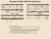
academia₅₀;6040422 said:
Thank you.
The link had everything needed.
Here is a SCREEN shot, annotated for clarity.
Hope you can clearly see it!
It is a screen shot…
Note that there are input 'volume knobs' on all models of the Behringer amplifiers. If you did not build a thing … but just split off the inputs to your amplifier, to also be input(s) to the Behringer stack, without needing resistor dividers or anything else, with 0.775 V sensitivity and a 10 kΩ input impedance, you're pretty much golden.
It was as I expected… actually.
I have never seen a commercial amplifier with '4 Ω' ionput impedance!
Usually 10 kΩ to well over 250 kΩ impedance.
Those are the “usual design numbers”
You might be asking, “why wouldn't all manufacturers standardize on one particular value?!?”.
That would be a fair question. The answer is surprising, yet very much a deeper inside view of the whole audio design world.
Ideally, we would want the lowest input impedance “practical”. Why?
To reduce, reduce and reduce to the minimum line-frequency hum.
The lower the input impedance, the less hum “makes it thru” from the outside.
Yet, the lower the input impedance, the more the source devices providing signal not only have to provide signal voltage but also power. Ah…
Then there are the realities of instruments without preamplifiers. My custom-wound guitar pickups can only provide the most tiny amount of current at any output voltage. They're very sensitive to the guitar strings, but unfortunately don't generate but a feather's worth of power. So, when the pre-amp, or amplifier they're plugged into has “only 10 kΩ” input, that just kills their output. Very low volume, and very muddy.
However, when the very same guitar is plugged into a “direct box” or a high-sensitivity (and quite common) guitarist's crate amplifier, their input jacks are designed for very high input impedance. 250 kΩ all the way up to 1000 kΩ. Then my custom pickups can sing!
The problem tho' is that the same box-amplifiers and direct-boxes are terribly prone to hum-pickup from the environment. One has to use quite-special and rather expensive quarter-inch instrument cables to squash (prevent) unpleasant levels of buzz and hum at high volume settings.
See?
We want LOW impedance inputs to squash noise. But when too low, the load on the source device increases … to unrealistic power production levels. And unamplified instruments, magnetic and piezoelectric pickups want really high input impedances to match their feeble (but beautiful) output.
Such tension!
Hence why almost every 'stage amp' (like the Behringers) has standardized on 10 kΩ / 20 kΩ input sensitivity. The same manufacturers have standardized on 600 Ω output power driving capability for all their mixer boards, and similar devices (shown in the pretty pictures in the PDF!).
As I said way above, 600 Ω output can drive 10,000 Ω input, easily. VERY easily. But 175,000 Ω output from one of my guitar pickups, can not drive a 10,000 Ω input without signal damage.
________________________________________
MY SUMMARY ADVICE … put a cable splitter between your preamp and amplifier, to 'tap' a second preamp output signal. Run that directly to the Behringer D-class subwoofer-intended amplifier. The Behringers have all kinds of front-and-back panel settings to assist. There is no need for you to first amplifier the source(s) thru your magnificent amplifiers, and then take that output, voltage-divide it, and send it to the subwoofer amp.
OK?
Respectfully,
⋅-=≡ GoatGuy ✓ ≡=-⋅
Attachments
That's a PA amp. You can connect the balanced hot and cold straight across the speaker terminals. If you want you can add 1k resistors in series of each lead. However as everybody else has said you must leave the original speakers connected or replace them with a dummy load 8R power resistor. If its a guitar valve amp you could mic it up (for lead) or use a DI box for bass.
Goatguy :
Yes, OK ! 😉
Thanks for the attachment, the screenshot is perfectly readable!
Lots of useful information there!
Let me study all that little, I have to refresh some somewhat forgotten knowledge of Ohmn's Law, and make some calculations ...
I will definitely not take a signal from the previous one with the PL, the signal will be taken from the secondary of the OPT.
For practical reasons, less connected and I do not want to "reach out" into the beast of 30 KG. (It has no separate pre-signal, it would have been very useful a bridge there, in the style of NAD 3020).
Best regards
Last edited:
That's a PA amp. You can connect the balanced hot and cold straight across the speaker terminals. If you want you can add 1k resistors in series of each lead. However as everybody else has said you must leave the original speakers connected or replace them with a dummy load 8R power resistor. If its a guitar valve amp you could mic it up (for lead) or use a DI box for bass.
Thanks for the information, it is Hi Fi, it is a home-use valve amplifier (Prima Luna) to which I will connect another SS amplifier exclusively for sub frequencies.
But it is not yet decided if I will buy the Bheringer, first I will see how two subwoofer cabinets I am building behave, with the current Dayton SPA250 board amplifier, Then I will make the decision, but I am finding out the possible setbacks that may arise.
academia₅₀;6042171 said:Goatguy Yes, OK ! 😉
So… in your setup do you have a preamp?
IF YES - then just buying or making a “splitter cable” is your easiest, wisest, and very likely least-troublesome way to achieve the results you have said you desire.
IF NO - then making a 2-resistor output-attenuator is your best bet.
And you have a fairly straight forward set of equations to allow it to happen. And if you don't like doing that, then I've already given you a pair of resistors that'll do the job, and do it well.
So… does your system use a separate preamplifier?
That is the question.
⋅-=≡ GoatGuy ✓ ≡=-⋅
Wow, I was waiting for that question ....
Preamplifier ? Yes, but because of my configuration I can't use the preamp for what you say.
Please look at post 12, tomorrow (with time) I will make a sketch .... Ok?
Thanks for your interest !
Preamplifier ? Yes, but because of my configuration I can't use the preamp for what you say.
Please look at post 12, tomorrow (with time) I will make a sketch .... Ok?
Thanks for your interest !
Finally I have purchased the Behringer NX3000D amplifier.
So I have to connect it to the speaker output of the Prima Luna valve amplifier.
Here they have provided me with a lot of valuable information in this thread, they are all appreciated and I am grateful for that.
So, I have to build the voltage shunt, I want to get as close as I can to the O.775 Volts for maximum output.
I found these calculators online, but should I use the more complex one, for AC (I don't know what j is here), or the simpler one for DC?
For AC
AC Voltage Divider
For DC
Calculadora de Un Divisor de Voltaje
And, what value of V In should you use in either case?
What is a typical output voltage for these valve push pull configurations on the secondary of the output transformer? What value should I choose for Vin? 20 Volts, 30 Volts, 40 volts? In my case, I use KT-88 or EL34 tubes, it delivers 38 watts in UL, in 8 Ohms.
DiaLogue Two — PrimaLuna USA
How can I measure the voltage delivered by my amplifier myself, I don't have an oscilloscope, only a multimeter, is it possible?
38 watts into 8 ohms is 16V.
It's incredibly improbable that you are using all 38W.
Your amp has 35dB of gain, which is ridiculously high. (20dB would be enough)
The NX3000D has 37dB of gain.
You will need to determine the difference in sensitivity between what the NX3000D drives and what the tube amp drives. Pad the output of the amp down a little less than that, then use the trim pots on the NX3000D to fine tune the levels. I would recommend a resistive pad of 1000 ohms total resistance.
16 Volts? I will then use 20 volts on the calculator as V in. in DC.
The amp should act as a general volume control, the Behringer's settings can be adjusted so as not to clutter up the input, I get that, thanks.
The amp should act as a general volume control, the Behringer's settings can be adjusted so as not to clutter up the input, I get that, thanks.
With R1 20 K and R2 1 K I get 0.982 Volts...
I'll play around changing values. You say you don't need to use the AC calculator ?
I'll play around changing values. You say you don't need to use the AC calculator ?
First make sure the output terminal 0 Ohm (common) tap is grounded, some aren't.
If so, connect the resistor divider between the 16 and 0 taps as follows.
Connect a 1k to the 0 tap, and a 20k to the 16 tap. Connect the
free ends of the resistors together, and to the hot cable conductor.
Connect the ground shield of the cable to the amplifier 0 Ohm tap.
If the level is too high, increase the 20k.
I had forgotten this .......😉 ( thanks rayma, perfect ! Behringer and other manufacturers have standardized 0.750 Volts to 0 dB, I think it will work , the DC calculator says that:
If ....
VIn 20 volts
R1 25 Kohms
R2 1 Kohms
then
Vout is 0,769230769231V
Behringer and other manufacturers have standardized 0.750 Volts to 0 dB, ( CoatGuy dixit ) I think it will work !
I will use these values, I will update you on the construction, thanks and take care Covid 19, please !
Last edited:
- Home
- Amplifiers
- Tubes / Valves
- How to take low level signal from an OPT ?