Only one opamp was on those regulators. No signal was fed to the circuit. Measurements were done while parts were pulling little current (q. curr.)Jusr FYI, asking those regulators to reduce input voltage by half (15V) AND deliver high current isn't going to work well for sound quality. Output impedance and load regulation deteriorate as Vin-Vout exceeds 4V...
I guess at this point my question is how to correctly wire attenuator for amplifier output and audio interface balanced input?
I have XLR connection for audio interface input.
When I use pin1(gnd) and pin2(sig+) I get a lot of interference.
When I connect pin2 and pin3 together, all of the interference is gone, but the level is twice as low.
Full description of the connection:
I take output from the amplifier (OUT+ and GND) and connect it to 8ohm 100W resistor.
Signal is then taken from the resistor and fed into attenuator consisting of two resistors.
Attenuator output is connected to the input of the audio interface.
Last edited:
You are close but a few connections need to be changed. input of the soundcard is differential meaning that its sensitive only to the difference between pins 2 and 3. If 3 is open it will follow 2 and show very little signal. Pin 1 is ground and should connect to the chassis of the DUT. Pin 3 should connect to the low side of the speaker connection. Ideally s you can work with BTL amps you would duplicate the R1 R2 connection on both pin 2 and pin 3 with the low side of both R3's connecting to pin 1. I hope my crude markup of your drawing makes sense.


New attenuator has resistors R2=9.1K and R3=1K for best noise performance.
I am using Focusrite 2i4 interface.
Still getting a lot of interference when measuring.
Tried changing power supply from linear to SMPS - did not fix the issue at all.
I am using Focusrite 2i4 interface.
Still getting a lot of interference when measuring.
Tried changing power supply from linear to SMPS - did not fix the issue at all.
Attachments
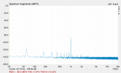
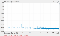

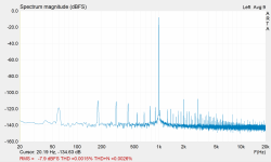
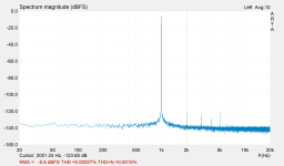
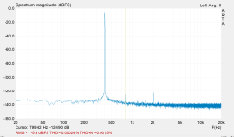
I revisited setup in ARTA and played with different settings for the Focusrite Scarlett audio interface and I was able to calibrate it properly ( at least I think I did) to the point where it shows pretty good performance.
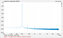
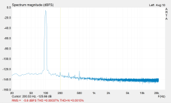
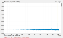
So this is the best that the audio interface can deliver so far:
I took measurements at 100Hz, 200Hz, 400Hz, 1kHz, 5kHz, and 9kHz.
At 1kHz THD is at 0.00027% and THD+N is at 0.0015%.
So this is the best that the audio interface can deliver so far:
I took measurements at 100Hz, 200Hz, 400Hz, 1kHz, 5kHz, and 9kHz.
At 1kHz THD is at 0.00027% and THD+N is at 0.0015%.
Attachments
-
 955mV_out_LINE_IN_at_2ocklock_PAD_5khz.PNG65.2 KB · Views: 72
 -
 955mV_out_LINE_IN_at_2ocklock_PAD_1khz.PNG63.6 KB · Views: 73
 -
 955mV_out_LINE_IN_at_2ocklock_PAD_0.4khz.PNG59.6 KB · Views: 66
 -
 955mV_out_LINE_IN_at_2ocklock_PAD_0.2khz.PNG66.6 KB · Views: 69
 -
 955mV_out_LINE_IN_at_2ocklock_PAD_0.1khz.PNG65.1 KB · Views: 64
 -
 955mV_out_LINE_IN_at_2ocklock_PAD_9khz.PNG64.4 KB · Views: 75
Last edited:
Check out Benchmark Audio's article on SMPS:
https://benchmarkmedia.com/blogs/ap...audio-myth-switching-power-supplies-are-noisy
https://benchmarkmedia.com/blogs/ap...audio-myth-switching-power-supplies-are-noisy
- Home
- Design & Build
- Equipment & Tools
- How to measure LM3886 power amp (what beginner tools to get)??