
At 126mV - that is output from Channel 1 of the Audio Interfaceat what voltage/power output?
without that its meaningless
Last edited:
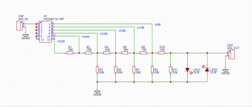
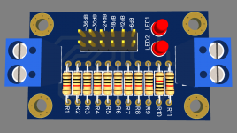
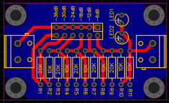
Now, to measure amplifier, I am looking at this attenuator schematics by Dan from Akitika.
Are those resistor dividers calculated correctly?
Will this work for measuring 45W in 8 ohm?
What LEDs can I use?
Edit: found pdf with Mouser part # for LED - 604-WP3A8GD
Thanks
Are those resistor dividers calculated correctly?
Will this work for measuring 45W in 8 ohm?
What LEDs can I use?
Edit: found pdf with Mouser part # for LED - 604-WP3A8GD
Thanks
Attachments
Last edited:
45W at 8 Ohm is 19V RMS so use -30dB or -24dB when at about max nominal power for 0.6V to 1.2V RMS at the card's input. That will keep its own THD contribution low enough and it will also be safe level for it.Will this work for measuring 45W in 8 ohm?
At 3.6V pk-pk (1.27VRMS Sine) the red Leds are going to clamp hard the input voltage of the card. Because red Leds usually have about 1.8V Vf. But they may start shining "clip" earlier before strongly lit. Green Leds can alternatively take it up to 4.4V pk-pk or 1.55V RMS hard clip.
In any case when clamping starts, even if softly at 1V RMS, the sinewave tops gonna get gradually clipped until well flattened out and you will see steep rise in THD spikes. There you should increase the attenuation step.
I would suggest to read ARTA Tutorial (Handbook) esp. parts 4 and 5 about how to calibrate soundcard:At 126mV - that is output from Channel 1 of the Audio Interface
https://www.artalabs.hr/support.htm
Part 5.4 is about testing the amplifier.
Unless your amp has balanced input, I would use SE RCA (unbalanced) output of your intarface.
Martin
Last edited:
I would suggest to read ARTA Tutorial (Handbook) esp. parts 4 and 5 about how to calibrate soundcard:
https://www.artalabs.hr/support.htm
Part 5.4 is about testing the amplifier.
Unless your amp has balanced input, I would use SE RCA (unbalanced) output of your intarface.
Martin
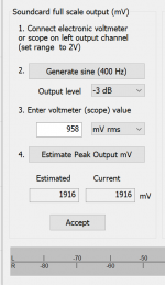
I was able to find the English version of the manual and followed calibration instructions.
I have set up the main volume on the Focusrite audio interface to the max. Also, adjusted "direct monitor" all the way to "playback".
After measuring output with my voltmeter I get 958mV reading. I am measuring balanced output as the amp I intend to test has balanced inputs.
Plugging those values into ARTA gives 1916mV. I used mV rms. Should I use mV pk? I have Fluke 115 - not sure if it measures rms or pk voltage?
Attachments
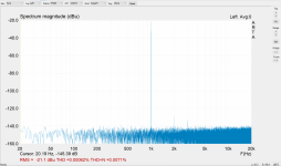
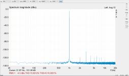
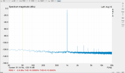
With new calibration settings I get different THD and THD+N figures in ARTA.
THD is 0.0012%
THD+N is 0.0031%
THD+N figure improved from previous measurement. THD got worse though.
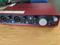
Settings on Focusrite audio interface:
Main volume on 12 o'clock
Direct monitor knob fully on playback
Input 1 switch is on INST
Input 1 pad is engaged
Input level is 12 o'clock
THD is 0.0012%
THD+N is 0.0031%
THD+N figure improved from previous measurement. THD got worse though.
Settings on Focusrite audio interface:
Main volume on 12 o'clock
Direct monitor knob fully on playback
Input 1 switch is on INST
Input 1 pad is engaged
Input level is 12 o'clock
Attachments
Last edited:
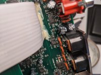
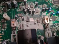
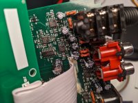
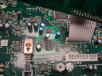
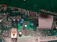
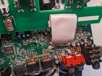
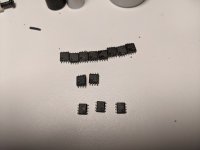
Audio interface was opened and inspected for interior parts:
Main ADC/DAC chip is CS4272 with -114dB Dynamic Range and -100dB THD+N specs
About a dozen of NJM4565 used in audio path. THD is unknown.
I am considering swapping those with LM4562 soic chips. Is it worth it, anyone?
Main ADC/DAC chip is CS4272 with -114dB Dynamic Range and -100dB THD+N specs
About a dozen of NJM4565 used in audio path. THD is unknown.
I am considering swapping those with LM4562 soic chips. Is it worth it, anyone?
Attachments
-
 PXL_20220804_005838505.jpg328.8 KB · Views: 90
 -
 PXL_20220804_005701120.jpg530.6 KB · Views: 86
 -
 PXL_20220804_005817890.jpg399.2 KB · Views: 84
 -
 PXL_20220804_005828179.jpg365.3 KB · Views: 90
 -
 PXL_20220804_005622562.jpg540 KB · Views: 89
 -
 PXL_20220804_005651186.jpg543.1 KB · Views: 91
 -
 PXL_20220804_005640729.jpg465 KB · Views: 87
 -
 PXL_20220804_005930699.jpg450.6 KB · Views: 84
 -
 PXL_20220804_005923429.jpg466.9 KB · Views: 91
Last edited:
That's normal because you used stronger test signal than before. Signal to noise floor distance increases but residual THD gets pushed up a bit with level.THD+N figure improved from previous measurement. THD got worse though.
Expect marginal gains at most. If not GBWP spec and decoupling/layout incompatibility problems making it worse. IMHO don't mod it. Its a low noise low THD interface possibly best in price class as is. Its the ADC chip section that mainly sets the test loop's SINAD (inverse THD+N) max dB performance.I am considering swapping those with LM4562 soic chips. Is it worth it, anyone?
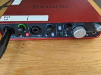
Also, try with TRS out to XLR Mic in cable if you got one (with the input gain knob set at minimum). Front combo jack TRS Line-in usually has not the best obtainable spec in such interfaces.
Expect marginal gains at most. If not GBWP spec and decoupling/layout incompatibility problems making it worse. IMHO don't mod it. Its a low noise low THD interface possibly best in price class as is. Its the ADC chip section that mainly sets the test loop's SINAD (inverse THD+N) max dB performance.
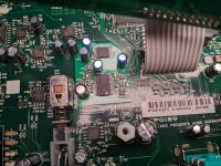
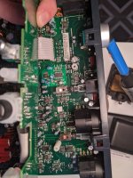
I did not have patience and went ahead with the mod. All but 4 NJM4565 chips got replaced with LM4562. For headphones OPA1688 got installed. For 2122 chips I soldered in OPA1602.
Attachments

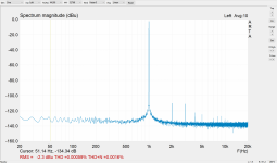
With the same settings THD is lower, but noise is up now.
That is with the INST switch on the input engaged.
PAD is engaged too.
Looks like I will have to swap 2122 back in...
That is with the INST switch on the input engaged.
PAD is engaged too.
Looks like I will have to swap 2122 back in...
Attachments
Last edited:
From the manual:
Line input THD+N: <0.01% (‘A’-weighted, 16 dB input gain, -1 dBFS output, 20 Hz – 22 kHz filter)
Inst input THD+N: <0.0025% (‘A’-weighted, 16 dB input gain, -1 dBFS output, 20 Hz – 22 kHz filter)
Line outputs 1 & 2 (balanced): <0.0015% (-1 dBFS input, 1 kHz, 20 Hz – 22 kHz)
Line input THD+N: <0.01% (‘A’-weighted, 16 dB input gain, -1 dBFS output, 20 Hz – 22 kHz filter)
Inst input THD+N: <0.0025% (‘A’-weighted, 16 dB input gain, -1 dBFS output, 20 Hz – 22 kHz filter)
Line outputs 1 & 2 (balanced): <0.0015% (-1 dBFS input, 1 kHz, 20 Hz – 22 kHz)
- Home
- Design & Build
- Equipment & Tools
- How to measure LM3886 power amp (what beginner tools to get)??