Your interface has max. balanced output level +10 dBu (according to the manual) or 2,45 Vrms (for 0 dbFS). For calibration you use -3 dBFS which gives 1,73 Vrms. Your measured value of 958 mV seems too low. Or you have measured only one leg of the balanced output.I was able to find the English version of the manual and followed calibration instructions.
I have set up the main volume on the Focusrite audio interface to the max. Also, adjusted "direct monitor" all the way to "playback".
After measuring output with my voltmeter I get 958mV reading. I am measuring balanced output as the amp I intend to test has balanced inputs.
Plugging those values into ARTA gives 1916mV. I used mV rms. Should I use mV pk? I have Fluke 115 - not sure if it measures rms or pk voltage?
Martin

Decided to check improvements on input channel 2. It shows rather noisy response. I then proceeded to disconnect anything from the interface, but the channel remains noisy. Tried switching between LINE / INST, engaging/disengaging the pad, changing volume. I even tried setting up generator to the channel 3 and 4. No luck.
I got three assumptions:
I got three assumptions:
- either I messed it up while modding
- previous owner overloaded the channel
- flaw in design / failed qc from the factory
Attachments
Here's what I foundFrom the manual:
Line input THD+N: <0.01% (‘A’-weighted, 16 dB input gain, -1 dBFS output, 20 Hz – 22 kHz filter)
Inst input THD+N: <0.0025% (‘A’-weighted, 16 dB input gain, -1 dBFS output, 20 Hz – 22 kHz filter)
Line outputs 1 & 2 (balanced): <0.0015% (-1 dBFS input, 1 kHz, 20 Hz – 22 kHz)
Just like you said, THD goes from the best with mic input 0.002% to instrument input 0.0025 to line input 0.01Weird input spec quotes. Usually mic betters line that betters instrument due to the rise in noise with increased impedance. Anyways, confirm factory spec, change the scale from dBu to dBFS and shoot.
Your interface has max. balanced output level +10 dBu (according to the manual) or 2,45 Vrms (for 0 dbFS). For calibration you use -3 dBFS which gives 1,73 Vrms. Your measured value of 958 mV seems too low. Or you have measured only one leg of the balanced output.
Martin
I measured one leg of the input - tip of the jack + sleeve. I have cable with TRS jacks on each side - will it feed full differential signal when I plug it into XLR/TRS jack input? I am not sure, need to do some research
FYI, you can also use the Digilent WaveForms program with your Scarlett. I would go with the latest beta version.
https://forum.digilent.com/topic/8908-waveforms-beta-download/
https://forum.digilent.com/topic/8908-waveforms-beta-download/
Decided to check improvements on input channel 2. It shows rather noisy response. I then proceeded to disconnect anything from the interface, but the channel remains noisy. Tried switching between LINE / INST, engaging/disengaging the pad, changing volume. I even tried setting up generator to the channel 3 and 4. No luck.
I got three assumptions:
My guess they messed up something with ADC input to the CS4272 chip
- either I messed it up while modding
- previous owner overloaded the channel
- flaw in design / failed qc from the factory
This got fixed by replacing one of the 2122 ic. My assumption is that someone overloaded that channel and damaged the first IC on the analog signal path - that is 2122 chip. Replacing those with OPA1602 created excessive noise. Trying OPA1612 now and it seems like it is working fine.
Interesting that now having one channel with 2122 ic and second channel with opa1612 I had an opportunity to test both channels and compare them and it shows that they both perform identical THD and noise wise.
Last edited:
Here are the results after the mod.
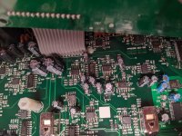
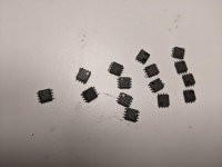
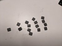
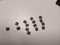
I decided to replace both 2122 with OPA1612, $5
Headphone opamp got swapped to OPA1688, $1.30
9 opamps were swapped with LM4562 (only had 10 of those in SOIC package) $1.00
4 opamps near RCA ouputs got swapped with NE5532A $0.35
Total cost of mods is less than $25
Both channels function properly now.
Attachments

Last edited:
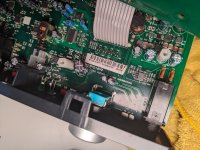
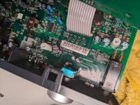
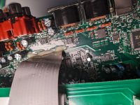
Photos of the modded board are attached with this post.
I had a lot of fun!
I had a lot of fun!
Attachments
-
 PXL_20220805_011452609.jpg619.2 KB · Views: 104
 -
 PXL_20220805_011456687.jpg519.5 KB · Views: 108
 -
 PXL_20220805_011502142.jpg478.1 KB · Views: 98
 -
 PXL_20220805_011501063.jpg495.9 KB · Views: 92
 -
 PXL_20220805_011522549.jpg491 KB · Views: 94
 -
 PXL_20220805_011513382.jpg487.5 KB · Views: 92
 -
 PXL_20220805_004311096.jpg323.4 KB · Views: 89
 -
 PXL_20220805_004307184.jpg307.2 KB · Views: 87
 -
 PXL_20220805_004306666.jpg311 KB · Views: 104
Best THD+N in your latest graphs is Line in 0.0015%. That is -96.5dB. Maybe through MIC in XLR it can also achieve the -100dB codec chip's spec. Certainly outperforms the majority of power amps. Except very few SOTA high efficiency modern designs in the market. Thus very good for testing. Remains to build the attenuator.
Not sure if there's a clear THD+N performance gain than before swapping the op-amp chips but you had fun and that's the main thing in a hobby.
Not sure if there's a clear THD+N performance gain than before swapping the op-amp chips but you had fun and that's the main thing in a hobby.
Yeah, I ordered those attenuator boards, just waiting for them in the mail...Best THD+N in your latest graphs is Line in 0.0015%. That is -96.5dB. Maybe through MIC in XLR it can also achieve the -100dB codec chip's spec. Certainly outperforms the majority of power amps. Except very few SOTA high efficiency modern designs in the market. Thus very good for testing. Remains to build the attenuator.
Not sure if there's a clear THD+N performance gain than before swapping the op-amp chips but you had fun and that's the main thing in a hobby.
did you limit the BW of Arta 20-20K according to the standard THD+N? Without that limiting, Arta will be noticeable less optimistic than AP analyzers.
I tried both with loading the file you supplied (20-20k limit) and without. Seems that THD is the same for both cases. I use Fs at 44100Hz, maybe that is why. When I use 96000Hz and with your file THDs are lower.did you limit the BW of Arta 20-20K according to the standard THD+N? Without that limiting, Arta will be noticeable less optimistic than AP analyzers.
Found this thread where a guy is using E-MU 1616m with super low distortion - https://www.diyaudio.com/community/...undcard-and-arta-software.312216/post-5185610
Was able to measure few things with my setup.
I have LM3886 board that was mounted on a heatsink and loaded with dummy 8 ohm load.
Power was provided by linear power supply using Antek 22V-0V-22V transformer with 14,000uF caps per rail. +-15V was obtained with LM317/LM337 regulators.
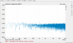
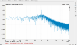
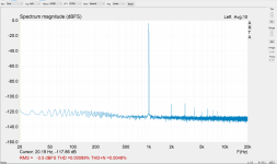
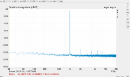
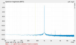
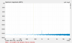
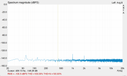
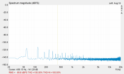
I am attaching four results:
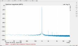
Conclusion - I need better power supply for +-30V.
I have LM3886 board that was mounted on a heatsink and loaded with dummy 8 ohm load.
Power was provided by linear power supply using Antek 22V-0V-22V transformer with 14,000uF caps per rail. +-15V was obtained with LM317/LM337 regulators.
I am attaching four results:
- Audio interface loopback - best result
- Audio interface - nothing plugged in to the input - another best result
- Connected to amplifier via attenuator board with amp off
- Amp on but no signal in - clearly power supply has some noise inserted up to -110dB
Conclusion - I need better power supply for +-30V.
Attachments
Jusr FYI, asking those regulators to reduce input voltage by half (15V) AND deliver high current isn't going to work well for sound quality. Output impedance and load regulation deteriorate as Vin-Vout exceeds 4V...
Actually that mains noise isn't so bad. It's hard to get lower than -100dB. It could be the power supply as such, but also the wiring run and grounding scheme.
You could see what it looks like when using a separate lab supply (maybe you already did that).
Jan
I don’t have lab supply- but I have Connex SMPS300RS board that I want to use to measure in the nearest future hopefully…
- Home
- Design & Build
- Equipment & Tools
- How to measure LM3886 power amp (what beginner tools to get)??