Hi, Kanwar,
Thanks alot 😀
I will study it. Like Pierre said, how to connect the speaker output? Is it needing 2 of them to become full bridge?
Thanks alot 😀
I will study it. Like Pierre said, how to connect the speaker output? Is it needing 2 of them to become full bridge?
Pierre said:Some comments for Kanwar.
Your schematics is for only a section of a full-bridge amplifier, isn't it? If not, your output must be AC coupled, or there will be a +HRail/2 DC component at the output. (and AC coupling at the output is something we really don't like in high power amplifiers)
You don't use feedback as well, that would be very nice and I think it won't be difficult to achieve.
Best regards,
Pierre
The output is DC coupled ..... not AC coupled because this is meant for H-Bridge topology not a Half bridge .....
Due to BD mode modulation , the feedback is not much necessary when the prime target is low frequency amplifier ...
lumanauw said:Hi, Kanwar,
Thanks alot 😀
I will study it. Like Pierre said, how to connect the speaker output? Is it needing 2 of them to become full bridge?
2 units are required for bridging ...
For 2 Bridged Units the Oscillator must be Synchronised i.e. CT pin of 2 IC's must be tied together and shunted to GND by the Capacitor chosen for desired frequency...Master IC's pin Rt is connected to resistor to GND...but Slave IC's pin Rt must be tied to VREF...for proper Sync......
regards,
K a n w a r
lumanauw said:Hi, Kanwar,
Thanks alot 😀
I will study it.
David_ The LumanauW,
What are your findings after the study of my schematics.......
K a n w a r
Hi, Kanwar,
I haven't build it yet. I still thinking about how to use symmetrical rails (+/-35VDC), make it full bridge, and to put feedback on it. I still don't know it is better feedback before or after LC filter?
You have any idea how to implement those?
I haven't build it yet. I still thinking about how to use symmetrical rails (+/-35VDC), make it full bridge, and to put feedback on it. I still don't know it is better feedback before or after LC filter?
You have any idea how to implement those?
Hi David,
In my opinion Single supply Full Bridge Class-BD mode[dont use Class-AD] without feedback would be adequate as long as your aim is for sub woofer application amp
K a n w a r
In my opinion Single supply Full Bridge Class-BD mode[dont use Class-AD] without feedback would be adequate as long as your aim is for sub woofer application amp
K a n w a r
Hi, Kanwar,
I haven't made it yet. I get stuck in how to make it full bridge amp. I've got IR2111, but have no idea how to make full bridge with SG3524.
I haven't made it yet. I get stuck in how to make it full bridge amp. I've got IR2111, but have no idea how to make full bridge with SG3524.
lumanauw said:Hi, Kanwar,
I haven't made it yet. I get stuck in how to make it full bridge amp. I've got IR2111, but have no idea how to make full bridge with SG3524.
Its very easy ...connect another CMOS inverter to get the inverted signal from the output of SG3524 to drive another IR2111, or use 2 seperate halfbridges to form a fullbridge....and you have 3 Level PWM as free gift...
K a n w a r
Bump!
I´ll be testing this lofi d-amp thing before i give up completely. I´ll make it halfbridge tho, but i know a solution called split supply with the speaker gnd referenced to the centertap. If it doesent work i may try full bridge, but with one change. Two SG2524 should not be needed for fullbridge, just use an inverter to invert the signal to the other gate driver.
I think it should work. What do you think ?
Heres a schem with my idea:
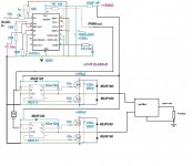
Hi Tekko,
The schematic is right..you could now take another step towards prototyping it as well..
regards,
K a n w a r
The schematic is right..you could now take another step towards prototyping it as well..
regards,
K a n w a r
Ok. I hope your right. Thoo bad that inverters dont come as single devices, but just six @ at time.
Maybe a resistor and transistor approach would work, i could try it.
I want a simulator that contain these ic´s, i wanna be sure that it works before i order the parts.
Maybe a resistor and transistor approach would work, i could try it.
I want a simulator that contain these ic´s, i wanna be sure that it works before i order the parts.
Hi Tekko,
As far as simulators go these days I'd go for LTspice, it is at least bug free as far as I can see, (in terms of stability) and while it doesn't include many models it's not that hard to add them to it.
This may help you in your research in fact, you can research what component is best for the job that suits both your needs (cost and availability) and those of your circuit, and then add the model statement.
I've used several simulators and while I find analysis features somewhat limited on LTspice, certain avide users of it like analogspiceman have demonstrated it's also a matter of creativity.
It's also extremely easy to get the hang of compared to the others I've tried, and alot of people seem to be leaning that way, so the odds of getting help with it when required are pretty good.
Also, since I am the UCD salesman around here, if you want to build a really cool circuit you should take a close look at the DIY ucd projects around here. There are no IC's required, just your average small signal transistors.. and some nice mosfets which are free samples. There's an extremely good amount of information to be learnt in that, cost you pennies to make, and in the end it's bound to sound amazing.
- Status
- Not open for further replies.
- Home
- Amplifiers
- Class D
- How to fix this sch?