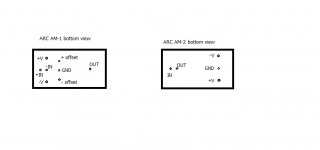
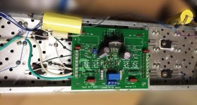
Right, so to answer all you who wants to see what my replacement modules looks like, here they are attached.
Use 1/2 watt resistors for 100 ohms and 369 ohms.
No heat-sinks are necessary for any of the 2N3440's or 2N5415's.
The J-Fets in AM-1 (Q1+Q2) can be substituted with other types, just trim R1 and R4 to an idle-current of 1-3mA and you are all good. The cascodes (Q5 + Q8) ensures a drain-source voltage around 5,5 volts.
Please also:
1) Check the supply voltages!!! I had collapsed voltage regs for AM-1 which gave me a much higher voltage and is probably the reason for the destruction of the modules to begin with.
2) Check your output stage !!! With the main PCB dismounted from the frame, you should definitely check that the output stage is working properly.
...both of these points require the schematic for the complete amplifier, which you can get here.
Please notice:
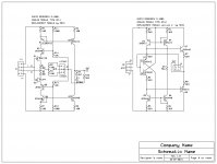
These modules are not 100% identical to the original ones, but I cannot get a complete circuitry and component types of those, so this is a valid shot, although improvements can definitely be made. Your suggestions are welcome.
At least the frequency compensation in AM-1 (R9 + C1 + R10),which is just copied from the original module, can probably be optimized to this particular circuit.
good luck 😎
Use 1/2 watt resistors for 100 ohms and 369 ohms.
No heat-sinks are necessary for any of the 2N3440's or 2N5415's.
The J-Fets in AM-1 (Q1+Q2) can be substituted with other types, just trim R1 and R4 to an idle-current of 1-3mA and you are all good. The cascodes (Q5 + Q8) ensures a drain-source voltage around 5,5 volts.
Please also:
1) Check the supply voltages!!! I had collapsed voltage regs for AM-1 which gave me a much higher voltage and is probably the reason for the destruction of the modules to begin with.
2) Check your output stage !!! With the main PCB dismounted from the frame, you should definitely check that the output stage is working properly.
...both of these points require the schematic for the complete amplifier, which you can get here.
Please notice:
These modules are not 100% identical to the original ones, but I cannot get a complete circuitry and component types of those, so this is a valid shot, although improvements can definitely be made. Your suggestions are welcome.
At least the frequency compensation in AM-1 (R9 + C1 + R10),which is just copied from the original module, can probably be optimized to this particular circuit.
good luck 😎
Attachments

Last edited:

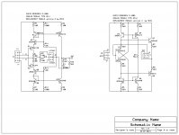
First improvement/correction...I reviewed what I actually build and this is it (sorry).
The difference is in AM-2 where the idle current is uncontrolled in the previous shown circuit. What I actually build - and which secures an idle current of approx 1.9 mA through both input and output transistors - is version 2.
...Oh I forgot to mention:
The amplifier is working fine with these modules and it is playing great.
Attachments


Many thanks Nrik. The circuit has an error AM-1.
I built one module test tomorrow.
Correct, that is an error - should be as muadib put it.
Module 2 has the same error.
Well spotted - thanks.
module AM-1 work, 🙂Correct, that is an error - should be as muadib put it.
Module 2 has the same error.
Well spotted - thanks.
Great to hear of another confirmed fix Maudib 🙂
corrected schematics:
Hello Henrik,
Please, let me know...
Your best choice for these 2SJ74/SK170 suffix ( IDSS classification ) :
- GR = 2.6~6.5 mA ?
- BL = 6.0~12 mA ?
- V = 10~20 mA ?
Many thanks for your nice contribution,
Raymond
My D-115 had similar (broken) module. It now has a Texas Instruments/NatSemi driver chip.
D-115 ?
A tube amp !
Possible you thought instead a D-110 one
Raymond
Mine is a D-120, sorry for the mistake.
D-120 ? I understand now.
In fact, the latest version of the D-100 and thus the most accomplished.
Please Jackinnj, could you tell me what "Texas Instruments / NatSemi driver chip" have you fitted in place of this ARC dead module ?
My greetings from France,
Raymond
D-120 ? I understand now.
In fact, the latest version of the D-100 and thus the most accomplished.
Please Jackinnj, could you tell me what "Texas Instruments / NatSemi driver chip" have you fitted in place of this ARC dead module ?
My greetings from France,
Raymond
Right now it has an LM4702 driving Renesas lateral MOSFETs. At one time it had an LM4702 driving TIP142/147 Darlingtons. As you know, the LM4702 can't provide enough drive current for ordinary bipolar devices.
Plan is to have LME49830 with Toshibas, but i haven't burned a PCB for this chip.
Right now it has an LM4702 driving Renesas lateral MOSFETs. At one time it had an LM4702 driving TIP142/147 Darlingtons. As you know, the LM4702 can't provide enough drive current for ordinary bipolar devices.
Plan is to have LME49830 with Toshibas, but i haven't burned a PCB for this chip.
Thanks !
Raymond
Are these amplifiers even worth saving??? They garnered a bad reputation when they were new and ARC discontinued them rather abruptly.
Mark
Mark
Are these amplifiers even worth saving??? They garnered a bad reputation when they were new and ARC discontinued them rather abruptly.
Mark
They came by me cheaply -- here's the rub -- the power xfmr, heatsinks and chassis were worth it.
Can I say this? The designs seem overly fussy, but who am I to judge?
Hello Henrik,
Please, let me know...
Your best choice for these 2SJ74/SK170 suffix ( IDSS classification ) :
- GR = 2.6~6.5 mA ?
- BL = 6.0~12 mA ?
- V = 10~20 mA ?
Many thanks for your nice contribution,
Raymond
Hi Raymond
I used BL but you can use the others or they can be substituted with other types, just trim R1 and R4 to an idle-current of 1-3mA and you are all good.
Any thoughts as to what to check for an amp with D-C offset in both channels?
_________________
Regards
Alley
_________________
Regards
Alley
Any thoughts as to what to check for an amp with D-C offset in both channels?
If the offset is the same in both channels I would start by chekcing the supply voltages. It has +/- 55V, 50V and 15V.
The +/- 55V supplies are regulated from +/- 75Volt.
Get the schematics here
- Home
- Amplifiers
- Solid State
- How to fix the Audio Research D-110 modules