Great. I think I am in same position right now as both my outputs have very little offset and haven't yet made up the new board for AM-2.
I did some more probing on the preamp board with the original AM-1. AM-2 modules(mine are ok). I notcied a few voltage discrepencies between channels.
Also the left channel had a nice sine wave output from AM-1, where the right chanell part of the lower sine wave was gone.
After ohming things out the right LM308N chip was not drawing any power. The left one was ok, the right one had issues.
I had some 8 pin sockets around so I unsoldered and put both sockets in. Sure enough, I took the LM308N from the left channel and put it in the right and the sine wave was perfect and left channel it had the same distortion. I thought the left might have had issues as that was the side that I had the new board burn up a bit. So it was hard finding the chips as a lot of guitar players are using them in Rat pedals, I guess for distortion, and there are a lot of fakes out there.
Any way found a couple and will wait till they get here. I wanted to make sure everything is ok before putting in those new boards again. It looks like everything else is ok now on the board and I also installed those new 4 2200uf/100v caps to replace the 1900uf ones.
thank you so much for your suggestionYeah, it looks like the 340's are backwards on your modules; the heat sink should face the broad solid line of the silk screen, if I understand the updated instructions correctly: The boards weren't labeled correctly in the initial pcb layout builds, the square pad that normally indicates the base orientation was placed on the incorrect pin for the 340's (it was ok on the 350's). And if I'm understanding, it was easier to address the issue in the silk screening rather than redoing the pcb layout...Anyway, both you and "Deafby" have way more experience in electronics than I do, I'm just a tinkerer, and I sometimes get unlock harsh criticism too when I'm slow to pick up on a point so I can understand your feelings -- "Deafby" has a real job, plus he's doing all of this design and support for our community, so I cut him a lot of slack. I think you're doing great and you're so close to finishing; and just think how sweet the amp will sound when you're finally done! Plus you'll have a great "I survived" story to tell to friends. ;-)
Hey any updates on your amp? I got a new LM308N chip, I haven't installed it yet, been working on other projects.Well, finally got the ARC amp reassembled and did a first power-on...Had a short but on the other channel, thank god for dim bulbs and variacs! I didn't get past 35V so I powered it off and rechecked the wiring, and sure enough, I there was a problem on one of the common connections. So I fixed that and tried the power-on again, and voila! Not even a flicker on the dim bulb at full voltage. I need to tidy up the wiring a bit an then check the dc offsets but I think this is decent progress for this weekend.
No update right now...Been doing car stuff and other related "Honey Do's" but I expect to get stuck back into it this weekend; I really don't have much more to do, so I expect about 4-hrs to close this out, unless the gremlins got to it while I wasn't watching. BTW, I replaced both the LM308N chips during my recap exercise, because I had no real way to assure myself that the chips were good and it's such a pain to take things apart.
Ya I have to get back to mine working on a few tube amps , then back to the 100B. That was weird how I discovered my bad LM308N chip.
Ok, just a quick update...We'll it mostly works BUT, I didn't change the two power transistors on the mainboard in my initial purge of old transistors, and well, of course it bit me on the A$$.
Both of those transistors tested good, but one of them (coincidently, the one on my problem channel) has a high leakage at full voltage, which shows up as a mild short thru the dim bulb...Ok, now out comes the main board and the both of the transistors got replaced but as of this moment, the mainboard hasn't been reinstalled into the amp -- Soon, trust me, soon....
My advice regarding DIY restoring the D100 series amps by Audio Research hasn't changed, don't! But, if you must, be sure you absolutely purge every single transistor in the unit and replace with quality parts from a reputable dealer at the inception of the project; otherwise, like me, you'll be doing it piecemeal later...Mind you, you could get lucky if your amp wasn't abused like my was, but it's a real pain to take these things apart even once, and I've had mine apart, for various reasons, at least six times...It's really starting to look like reef material to me.
Ya have to get back to mine, had to do a few repairs to a small Eico amp for a fellow. The transistors you didn't change you mean the 2 on the preamp board which look like they are part of a regulator power supply to get the 55 volts? Or you mean a couple on the main power board?
Yes that is one of the worst amps I ever worked on to take apart and get at at stuff. It reminds me of a Chinese Integrated tube amp..a Yaquin I think, it had issues in the predriver and you had to unscrew all bolts on the some of the transformers and lift them out enough to get at the board. Nice when you have something easily accessable. Let you know when I get back to mine. I have the new AM-1, AM-2 boards all fixed and ready to install back in.
Yes that is one of the worst amps I ever worked on to take apart and get at at stuff. It reminds me of a Chinese Integrated tube amp..a Yaquin I think, it had issues in the predriver and you had to unscrew all bolts on the some of the transformers and lift them out enough to get at the board. Nice when you have something easily accessable. Let you know when I get back to mine. I have the new AM-1, AM-2 boards all fixed and ready to install back in.
The two that are part of the regulator supply; they screw onto the board and one has a black wire and the other has a white wire under one of the screw heads...Yeah, easier to work on, but still have to do some desoldering on the wires to fully remove the board so I could work on it more easily.
Well I got back to mine today. I tackled the left channel where I had the board burn up. I installed the 2 new AM-1 AM-2 with them repaired and the transistors in the proper configuration. Slowly brought up variac and up to 50 volts no smoke or anything. Injected a 1khz signal and got 80v p/p+100 WRMS.
I then checked and I have +4.1V off offset. Wondering if when that board burned up it might of wacked of the new O/P transistors. But with it making full power that doesn't make sense? I'm not an expert on these high power SS amps. I will put the AM-1 and AM-2 in the right channel tomorrow if I get time and see what happens. My notes indicated before I had the board blow up on the left channel I had something like 24mv off set on the left channel, so something may have got wacked in the power section. If anyone else is following this, would I be looking in the left channel bank that has the +50v on it since I am getting +4.1v DC offset?
I then checked and I have +4.1V off offset. Wondering if when that board burned up it might of wacked of the new O/P transistors. But with it making full power that doesn't make sense? I'm not an expert on these high power SS amps. I will put the AM-1 and AM-2 in the right channel tomorrow if I get time and see what happens. My notes indicated before I had the board blow up on the left channel I had something like 24mv off set on the left channel, so something may have got wacked in the power section. If anyone else is following this, would I be looking in the left channel bank that has the +50v on it since I am getting +4.1v DC offset?
Update: I checked both power sections with the input terminated and got 45mv left channel and 28mv on the right channel. So left channel nothing got zapped.
Now both new AM-1, AM-2 boards have been installed in right channel. I get 80v p/p 100WRMS also. But here I have 6.8v DC offset.
So even with new boards I am getting some offset. The power section has been eliminated as working fine. Looking at the schematic possibly be the feedback causing the DC offset? I didn't pull out the orange wire coming from the predriver board to output terminal yet. This feed back goes to the LM308N chip, and the 4 diodes/zener, and I have tried a few different LM308N ones, no change. All voltages around that section and the diodes and 6.2 zener are ok. So I am chasing something in the predriver board. At least I know the amp section is good. My 55v and 15 volts are ok, just getting 13.55v .
Last edited:
Further update. I pulled the orange wire from output (feedback) and the DC is still there. I measured it on the input to the power section , therefore it is coming out of the new AM-2 board. I was reading back around page 7-8 and it was mentioned maybe Q33-Q36, these both feed back to the LM308N? I am also going to checkout the 55v and 15 as they are 1 volt or so low, the 75volts is ok. Keep you posted...hopefully a few of these parts are leaky, haven't checked any of them as I had other issues. This has been a long project...I guess it must of really got wacked hard before I bought it.
Offset is coming from the module more than likely. you probably damaged the driversWell I got back to mine today. I tackled the left channel where I had the board burn up. I installed the 2 new AM-1 AM-2 with them repaired and the transistors in the proper configuration. Slowly brought up variac and up to 50 volts no smoke or anything. Injected a 1khz signal and got 80v p/p+100 WRMS.
I then checked and I have +4.1V off offset. Wondering if when that board burned up it might of wacked of the new O/P transistors. But with it making full power that doesn't make sense? I'm not an expert on these high power SS amps. I will put the AM-1 and AM-2 in the right channel tomorrow if I get time and see what happens. My notes indicated before I had the board blow up on the left channel I had something like 24mv off set on the left channel, so something may have got wacked in the power section. If anyone else is following this, would I be looking in the left channel bank that has the +50v on it since I am getting +4.1v DC offset?
But the offset is in both channels and the the issuse was only in the left channel, I didn't power the right one for the 50 volts, had fuses pulled.
When I fixed the boards I checked the 2 Jfets and even replaced some of the other transistors, so everything tested ok.
So drivers you mean the Jfets or the 340/350 transistors?
When I fixed the boards I checked the 2 Jfets and even replaced some of the other transistors, so everything tested ok.
So drivers you mean the Jfets or the 340/350 transistors?
Doing some more thinking on all of this, when I had the left channel power section with only 20-30mv of DC offset and had the original AM-1, AM-2 modules I also had the 4-7 volts of DC offset, I think it might be something else on the circuit board causing this. I am going to do more checks on the board, rememeber before I bought it with blown outputs it got wacked with 130-140 AC volts and some spikes as per the original owner, so one of the transistors in the power supply could be causing this..keep you posted.
I went through entire predriver board and all voltages test ok.
The left channel with input shorted has 3.1v dc offset, the right channel boards (was the one that had burn up) it has 7.1vdc offset.Both the right channel boards were replaced and a few 340/350 transistors replaced that got wacked.
So here is my question: Since the DC offset on both boards is coming out of AM-1 and the right one had the burned board( has the Jfets that the board burned)-could the Jfet's have got stressed in both boards since the 340 were in backwards? The only thing left to do is get all new Jfets and 340/350's, I have 2 more sets of boards left.
I had the amp hooked up to my workshop speakers and it had no hum on either channel and sounded very nice, but would not want to run it for any length of time until this offset is completely gone.
Do you have a thermal camera? Depending on the failure, I've found it sometimes useful to see if I can find any hot spots; makes testing to see if anything is running unexpectedly warm...I just got a cheap flir attachment for my iPhone and it's been very useful when nothing else seems to work in identifying problem areas.
Camera is a nice idea. Nothing seems hot and actually running the amp this morning for about 10 minutes it runs a lot cooler than months ago. I guess replacing all the output transistors probably helped. It's something in the AM-1 boards that's causing the same DC that I am seeing on the output.
Deafbykhorns thought I might of damaged the the drivers. Not sure if he meant the Jfets or the 340/350 transistors. But the channel that has the Jfets that did the flareup has the higher DC, so maybe that's the issue. I did test everything before moving them to a new board. Maybe even some good 340/350 under full power are causing this where my cheap transistor checker is missing it. I'm in Canada so shipping from DIY Audio site is expensive, but I have a fellow next month sending me a tube amp from the US to restore, might get him to get me more Jfets, and put it in same box. Keep you posted but slowly getting there at least I'm getting 100 watts ch. I''l have to see what a camera adapter costs, I use Android phones.
Deafbykhorns thought I might of damaged the the drivers. Not sure if he meant the Jfets or the 340/350 transistors. But the channel that has the Jfets that did the flareup has the higher DC, so maybe that's the issue. I did test everything before moving them to a new board. Maybe even some good 340/350 under full power are causing this where my cheap transistor checker is missing it. I'm in Canada so shipping from DIY Audio site is expensive, but I have a fellow next month sending me a tube amp from the US to restore, might get him to get me more Jfets, and put it in same box. Keep you posted but slowly getting there at least I'm getting 100 watts ch. I''l have to see what a camera adapter costs, I use Android phones.
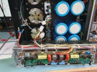
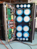
Update on the repair of a D110 Audio Research amp. In short: it runs! i made 4 modules with the Jfets in AM1. 2 modules for left and the same in a mirror configuration for the right channel. The pins aligned perfectly. A company in holland made me the boards that i designed. No problems with heat or DC offset on the output. A few millivolts, no problem.
But i went a little bit further in restoring this beast. The idea of filling 120.000 uf in one go is not ideal. So i installed a soft start that runs a big resistor of 16Ohm in the power line. After 6 seconds it overrides the resistor for the full 230V on the amp. The bulbs had to go to. I used 3x6 green leds attached trough a relais on the speaker protection board. So after about 16 seconds the speaker relais kick in and also the lights. Nice feature... The fuses in the speaker line had to go to. A new DC protection board takes care of DC output in the amps if something goes wrong and will switch the speakers off. The hart of the protection is the TA3717P. A reliable IC for the job.
The service manual suggets a 3K3 resistor (R128) for the power relais for 230V. Not a good idea. The voltage drop on the relais is to high. And C52 goes up in smoke. So i also added a 11K 5 Watt resistor extra in serie with R128 for a 110V voltage drop on the relais.
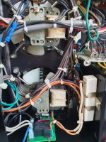
More stuff: Make the amp more servicable. I took the wires for the power and speaker wire apart (4), cut them and used rond crimpable connectors. Color on color, left and right. The wires for the extra power supply for the preamp (3) and the elco's on the chassis (3) and an extra earth wire combined in a 8 way crimp connector. The wires for the thermal switch apart in a similar 2 wire connector. This is live stuff, better apart. The current on the preamp power supply is about 50mA. no problem for a connector.
You can weld with the stored energy! So i used 10K resistors to unload the capacitors if the amp board is not connected. This is for 3 power supply circuits! If you test only the power supply the chassis is not connected to earth. A direct connection from the earth wire and the central 0 to the chassis fix this issue.
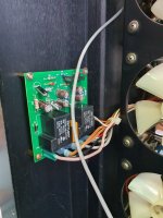
The service manual puts C54 on the input for DC protection on the input. And to protect the Jfets. Good idea. I made a small board to do so and made the elco somewhat better with a styroflex parallel.
This was a big project. Thank you readers for the support on this forum. The amp sounds good and it is nice to save a big boy like this one. Now i must figure out how to put it in the car.... LOL. 42 kilogram.
But i went a little bit further in restoring this beast. The idea of filling 120.000 uf in one go is not ideal. So i installed a soft start that runs a big resistor of 16Ohm in the power line. After 6 seconds it overrides the resistor for the full 230V on the amp. The bulbs had to go to. I used 3x6 green leds attached trough a relais on the speaker protection board. So after about 16 seconds the speaker relais kick in and also the lights. Nice feature... The fuses in the speaker line had to go to. A new DC protection board takes care of DC output in the amps if something goes wrong and will switch the speakers off. The hart of the protection is the TA3717P. A reliable IC for the job.
The service manual suggets a 3K3 resistor (R128) for the power relais for 230V. Not a good idea. The voltage drop on the relais is to high. And C52 goes up in smoke. So i also added a 11K 5 Watt resistor extra in serie with R128 for a 110V voltage drop on the relais.
More stuff: Make the amp more servicable. I took the wires for the power and speaker wire apart (4), cut them and used rond crimpable connectors. Color on color, left and right. The wires for the extra power supply for the preamp (3) and the elco's on the chassis (3) and an extra earth wire combined in a 8 way crimp connector. The wires for the thermal switch apart in a similar 2 wire connector. This is live stuff, better apart. The current on the preamp power supply is about 50mA. no problem for a connector.
You can weld with the stored energy! So i used 10K resistors to unload the capacitors if the amp board is not connected. This is for 3 power supply circuits! If you test only the power supply the chassis is not connected to earth. A direct connection from the earth wire and the central 0 to the chassis fix this issue.
The service manual puts C54 on the input for DC protection on the input. And to protect the Jfets. Good idea. I made a small board to do so and made the elco somewhat better with a styroflex parallel.
This was a big project. Thank you readers for the support on this forum. The amp sounds good and it is nice to save a big boy like this one. Now i must figure out how to put it in the car.... LOL. 42 kilogram.
Attachments

Wow what a beast!! I thought the D100B I am working on was heavy!! Never saw too many SS AR amps. I worked on a couple of the big tube models and owned a SP6B preamp. Thanks for sharing!!
So I had 2 more left over new boards and rebuilt them again with new Jfets and 340/350 transistors. There was a possible chance I was told something happened to them when the original boards were installed and the 340 were installed backwards...long story. Now with the new boards I am still getting approx 4 volts DC offset on both channels.
All the power supply is working fine, 15 volt, 55 volt and the main 50 volt supply. The amp works , it puts out 100 watts and even more at 1khz across 100 watt 8 ohm load. The DC offset is the same in both channels.
The 4 volt DC offset is present on the output of AM-2 (board) going to the power section. But I noticed if I disconnect the output wire going to the power section I have DC voltage coming from the power section. Looking at the schematic there is only one NPN which is on the input of the power section that has +50 volt rail connected, is something weird going on with these in both channels? All the output transistors have been replaced. With no inputs to the power section they are putting out under 40mv of DC offset, so the output section seems stable. The voltage coming from the input of the power section I think has the be the culprit and there is no blocking capacitor in this design. I have gone though all the 4 boards which solder to the output modules. Any help would be appreciated.
- Home
- Amplifiers
- Solid State
- How to fix the Audio Research D-110 modules